
- Kisan Kumar
- Bangalore
- Email is hidden.
233
Points
Questions
68
Answers
24
-
Here,\[ \phi \left ( x,y \right )=V_{\infty}x+\frac{5}{\sqrt{1-M_{\infty}^{2}}}e^{-2\pi\sqrt{1-M_{\infty}^{2}}y}sin2\pi x\]\[u=\frac{\partial \phi}{\partial x}=\frac{\partial }{\partial x}\left \{V_{\infty}x+\frac{5}{\sqrt{1-M_{\infty}^{2}}}e^{-2\pi\sqrt{1-M_{\infty}^{2}}y}sin2\pi x \right \} \]\[=V_{\infty}+\left \{ \frac{5}{\sqrt{1-M_{\infty}^{2}}}e^{-2\pi\sqrt{1-M_{\infty}^{2}}y}cos2\pi x \right \}2\pi\]\[=V_{\infty}+\frac{5\left ( 2\pi \right )}{\sqrt{1-M_{\infty}^{2}}}e^{-2\pi\sqrt{1-M_{\infty}^{2}}y}cos\left(2\pi x\right)\]\[v=\frac{\partial \phi}{\partial y}=\frac{\partial }{\partial y}\left \{V_{\infty}x+\frac{5}{\sqrt{1-M_{\infty}^{2}}}e^{-2\pi\sqrt{1-M_{\infty}^{2}}y}sin2\pi x \right \} \]\[=-\frac{5}{\sqrt{1-M_{\infty}^{2}}}\left (2\pi \sqrt{1-M_{\infty}^{2}} \right )e^{-2\pi\sqrt{1-M_{\infty}^{2}}y}sin2\pi x\]\[=-5\left ( 2\pi \right )e^{-2\pi\sqrt{1-M_{\infty}^{2}}y}sin\left ( 2\pi x \right )\]Speed of sound, \(a_{\infty} = \sqrt{\gamma RT}=\sqrt{1.4 \times 287\times 300}=347.189\,m/s\)
Mach number, \[M_{\infty} = \frac{V_{\infty}}{a_{\infty}}=\frac{200}{347.189}=0.576\]Therefore, at \(\left ( x,y \right ) = \left ( 0.07\,m, 0.07\,m \right )\)
\[u=200+\frac{5\left ( 2\pi \right )}{\sqrt{1-\left ( 0.576 \right )^{2}}}e^{-2\pi\sqrt{1-\left ( 0.576 \right )^{2}}\left ( 0.07 \right )}cos\left(2\pi \left ( 0.07 \right )\right)\]\[=224.272\,m/s\]\[v=-5\left( 2\pi \right )e^{-2\pi\sqrt{1-\left(0.576\right)^{2}}\left( 0.07 \right )}sin\left ( 2\pi \left ( 0.07 \right )\right )\]\[=-9.337\,m/s\]Velocity, \[V=\sqrt{u^{2}+v^{2}}=\sqrt{\left(224.272\right)^{2}+\left ( -9.337 \right )^{2}}=224.47\,m/s\]From isentropic flow properties, for, \[M_{\infty}=0.576,\frac{T_{\infty}}{T_{0}}=0.93777382\]\[T_{0}=\frac{300}{0.93777382}=319.9066\,K\]Speed of sound,\[ a_{0}=\sqrt{\left ( 1.4 \right )\left ( 287 \right )\left ( 319.9066 \right )}=358.5226\,K\]\[a^{2}=a_{0}^{2}-\frac{\gamma -1}{2}\left ( V^{2} \right )\]\[a^{2}=\left(358.5226\right)^{2}-\frac{1.4-1}{2}\left ( 224.47 \right )^{2}\]\[\Rightarrow a = 344.182\,m/s\]Mach number, \[M = \frac{V}{a}=\frac{224.47}{344.182}=0.6522\]From isentropic flow properties, for, \[M = 0.576, \frac{p_{\infty}}{p_{0}}=0.7986, \frac{T_{\infty}}{T_{0}}=0.93777\]From isentropic flow properties, for, \[M = 0.6522, \frac{p}{p_{0}}=0.7514, \frac{T}{T_{0}}=0.9216\]Therefore, at \(\left ( 0.07\,m,0.07\,m \right )\)
\[p = \left ( \frac{p}{p_{0}} \right )\left ( \frac{p_{0}}{p_{\infty}} \right )p_{\infty}=\left ( 0.7514 \right )\left ( \frac{1}{0.7986} \right )\left ( 1\,atm \right )=0.941\,atm\]
\[T = \left ( \frac{T}{T_{0}} \right )\left ( \frac{T_{0}}{T_{\infty}} \right )T_{\infty}=\left ( 0.9216 \right )\left ( \frac{1}{0.93777} \right )\left ( 300\, K \right )= 294.83\,K\]
- 1616 views
- 1 answers
- 0 votes
-
Inertial navigation system (INS): Inertial navigation system calculates the position, orientation and velocity of aircraft by using motion sensors that is
accelerometers and rotation sensors that is gyroscopes and computer. Inertial sensors are also supplemented with barometric altimeter and magnetometers. It also uses global navigation satellite system (GNSS) receiver. INS receives information from motion sensors and rotation sensors and data from global navigation satellite system (GNSS) receiver and provide information about absolute position in latitude, longitude and altitude and absolute attitude in terms of roll, pitch and heading to the host computer.The data received from global navigation satellite system improves accuracy of INS by compensating drift which occurs from small errors in data given by motion sensors and rotation sensors.
INS does not use any external references to find object’s position and orientation.
INS is used in aerospace applications, autonomous vehicles, robotics, industrial machinery mobile mapping etc.
Inertial reference system: Inertial reference system consists of gyroscopes, accelerometers, electronics system to calculate precise velocity, attitude and navigation information about an aircraft. Inertial reference system gives information about attitude, roll and pitch attitude, position, linear and angular velocity, linear and and angular acceleration, magnetic heading and true heading, azimuth tec.
Inertial reference system is the main component of the inertial navigation system and shows pilot the location of aircraft even when GPS signals are not received.
- 1857 views
- 1 answers
- 0 votes
-
Profile drag: Profile drag is the sum of of skin friction drag and pressure drag due to flow separation, which are due to the shape and size of the body that is due to the “profile” of the body.
Total drag coefficient for a finite wing is profile drag coefficient and induced drag coefficient.
Induced drag: Induced drag or drag due to lift is caused due to wing-tip vortices which trails downstream of the wing causing downwash, when an aircraft is in flight.
For the whole or complete airplane the total drag coefficient is sum of parasite drag coefficient which is composed of profile drag of the wing and friction drag of all other components that is exposed to the airflow, like fuselage, tail surfaces, landing gear and engine nacelles and induced drag coefficient. For transonic and supersonic speeds it also contains wave drag.
Wave drag: Wave drag is created at supersonic speeds by shockwaves.
Profile drag coefficient for a finite wing at a moderate angle of attack is almost same as its airfoil sections.
Total drag coefficient of the airplane varies as the angle of attack is varied because of change in the amount of separation of flow over airplane parts.
The sum of skin friction drag and pressure drag for a two-dimensional body is called the profile drag and for a three-dimensional body that is for a complete airplane, it is called the parasite drag.
Diagram for the variation of profile drag coefficient with Mach number which is showing the critical and drag-divergence Mach numbers and large drag rise near Mach 1.
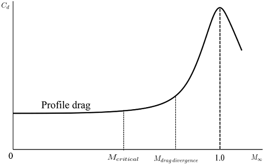 Variation of profile drag coefficient with Mach number
 At subsonic speed, profile drag coefficient is relatively constant with freestream Mach number. The variation of coefficient of drag with free stream Mach number is shown. Coefficient of drag is almost constant for Mach number from 0 to drag divergence, which is composed of profile drag. There is a very large increase in coefficient of drag between drag divergence Mach number and a little above Mach 1, which is due to the wave drag because of generation of shockwaves. For supersonic speeds coefficient of drag decreases.
Pressure drag which is due to flow separation is also called the form drag.
For subsonic speeds, total drag coefficient for a finite wing is sum of profile drag and induced drag.
For an airfoil, as the angle of attack increases, separation of flow over the top surface of the airfoil begins to occur giving rise to pressure drag or form drag.
The drag due to separation of flow is called the pressure drag due to flow separation and is also known as the form drag. Large pressure drag is mainly caused by blunt bodies like vertical flat plate and circular cylinders.
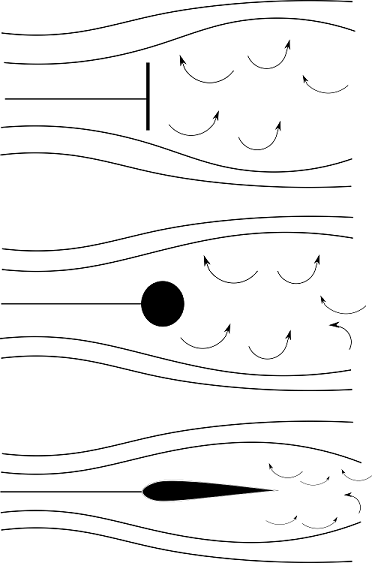 Separation of flow on different shapes
- 2207 views
- 1 answers
- 0 votes
-
Ailerons are one of the three basic controls on an airplane which are designed and used to change and control the moment. Ailerons can be deflected back and forth by pilot. Ailerons are mounted at trailing edge near the wing tips.
Deflection of ailerons changes the lift and moment of the wing. When one aileron is deflected up and the other aileron is deflected down, there is a creation of differential lifting force on the wings, generating a rolling moment.
This is also called lateral control, ailerons control roll.
The function of ailerons or other conventional control surfaces like elevators and rudder is to change one equilibrium position of the airplane to another and to produce nonequilibrium accelerated motions like maneuvers.
Ailerons are used to bank the aircraft by moving one wing tip up and other wing tip down. A downward deflection of aileron increases the lift. An upward deflection of aileron decreases the lift.
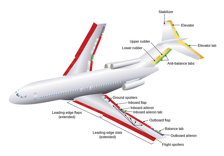 Flaps and ailerons in an aircraft
Flaps are a mechanism to generate high lift. The lowest speed at which an aircraft can fly in a straight and level flight is called the stalling speed.
In order to minimize stalling speed, coefficient of lift should be maximized, and at stalling speed there is maximum coefficient of lift.
A wing with a given airfoil shape, maximum coefficient of lift is fixed.
Lift produced by an airfoil depends on the physics of flow over the airfoil. Flaps, which are located at trailing edge of wing are used to increase the lift. When flaps are deflected downward, there is an increase in the camber of the airfoil with an increase in maximum coefficient of lift of the wing.
If the flaps are designed to translate rearward so that effective wing area is increased along with rotating downward, \(C_{L,\,max}\) can be increased by a factor of \(2\).
An aircraft has lowest flight velocities during take off and landing and flaps play critical role. During take off, flaps are set downward at a moderate setting, to have a high lift and low drag. During landing flaps and slats are deployed fully, so that there is a high lift and high drag.
Slats are moving parts which are present at the leading edge of the wing.
- 2061 views
- 1 answers
- 0 votes
-
The relation between lift slopes for an airfoil and wing is \[a = \frac{a_{0}}{1+\left ( \frac{a_{0}}{\pi AR} \right )\left ( 1+\tau \right )}\]Here, \(a_{0}\) = lift slope for an airfol, \(a\) = lift slope for a wing, \(AR\) = Aspect ratio,
\(\delta = \tau = 0.03\)\(0.102\, per\, degree = 5.8442\, per\, radian\)
Therefore, \[a = \frac{5.8442}{1+\left ( \frac{5.8442}{\pi \left ( 6 \right )} \right )\left ( 1+ 0.03 \right )}\]\[\Rightarrow a = 4.43\,per\,radian = 0.0773\,per\,degree\]Coefficient of lift for this wing will be\[C_{L} = a\left ( \alpha – \alpha _{L=0} \right ) =
0.0773\left ( 6^{\circ}-\left ( -\left ( 1.2^{\circ} \right ) \right ) \right )=0.55656\]Induced drag coeffcient for this wing will be \[C_{D,i} = \frac{C_{L}^{2}}{\pi AR}\left ( 1+\delta \right )
=\frac{\left ( 0.55656 \right )^{2}}{\pi \left ( 6 \right )}\left ( 1+0.03 \right )=0.0169\]- 1541 views
- 1 answers
- 0 votes
-
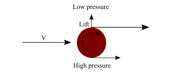
Lift per unit span produced by a circular cylinder with circulation, \(\tau\), is \[L^\prime=\rho _{\infty} v_{\infty }\tau\] This is also called the Kutta-Joukowski theorem. A spinning cylinder has a higher velocity at the top surface and a lower velocity at the bottom surface. Therefore, pressure at the top surface of the cylinder is lower than the bottom. This pressure difference creates a net upward force, which is called lift.
Since,\[L^{\prime}=\rho _{\infty} v_{\infty }\tau\]\[\Rightarrow 8=1.225\times 40\times \tau\]\[\Rightarrow \tau = 0.1633\]Therefore, circulation around the spinning circular cylinder is \(0.1633\, m^{2}/s\) .- 1550 views
- 1 answers
- 0 votes
-
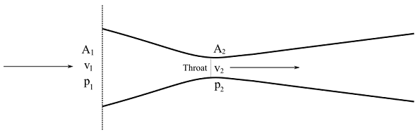
A venturi is a device which is used to measure the airspeed. It is a converging diverging duct. The inlet pressure and velocity of the duct is \(p_{1}\) and \(v_{1}\). At the throat of the duct velocity increases to the maximum, \(v_{2}\) and pressure decrease to minimum, \(p_{2}\). In the divergent section of the duct, velocity decreases and pressure increases. The inlet and throat area of the duct are \(A_{1}\) and \(A_{2}\).
Velocity of air is calculated using Bernoulli’s equation, which is\[v_{1}=\sqrt{\frac{2\left ( p_{1} – p_{2} \right )}{\rho \left [ \left ( \frac{A_{1}}{A_{2}} \right )^{2}-1\right ]}}\] Here, \(p_{1}\) is the atmospheric pressure, which is \(101325\,N/m^{2}\), \(p_{2}=100000\,N/m^{2}\),\(\frac{A_{2}}{A_{1}} = 0.8\).On putting the values, \[v_{1}=\sqrt{\frac{2\left ( 101325-100000 \right )}{1.225\left [ \left ( \frac{1}{0.8} \right )^{2}-1\right ]}}\]\[\Rightarrow v_{1}=62.015\,m/s\]Therefore, velocity of the airplane is \(62.015\,m/s\).
- 1758 views
- 1 answers
- 0 votes
-
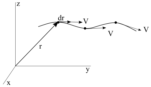
Velocity field is \(V=\left ( 3yt\hat{i}+5x\hat{j} \right )\)
In a streamline flow, velocity is tangent to the flow. \(V\) and \(dr\) is in the same direction. Therefore,
\[V\times dr=0\]Since, two vectors are in the same direction, their cross product is \(0\).
\[V\times dr = 0\]\[\Rightarrow \left ( 3yt\hat{i}+5x\hat{j} \right )\times \left ( dx\hat{i}+dy\hat{j} \right )=0\]
\[\Rightarrow \begin{vmatrix}
\hat{i} &\hat{j} &\hat{k} \\
3yt& 5x &0 \\
dx&dy & 0
\end{vmatrix}=0\]
\[\Rightarrow \hat{k}\left ( 3ytdy-5xdx \right )=0\]
At, time \(t = 3\)
\[\Rightarrow 9y\left ( 3 \right )dy -5xdx=0\]\[\Rightarrow 9ydy -5xdx=0\]\[\Rightarrow 9ydy=5xdx\]
On integrating
\[\Rightarrow \int 9ydy=\int 5xdx\]
\[\Rightarrow 9\int ydy=5\int xdx\]
\[\Rightarrow 9\frac{y^{2}}{2}+c_{1}=\frac{5x^{2}}{2}+c_{2}\]
\[\Rightarrow \frac{9y^{2}+2c_{1}}{2}=\frac{5x^{2}+2c_{2}}{2}\]
\[\Rightarrow 9y^{2}+2c_{1}=5x^{2}+2c_{2}\]
\[\Rightarrow 9y^{2}-5x^{2}=2c_{2}-2c_{1}\]
\[\Rightarrow 9y^{2}-5x^{2}=C\]At, point \((5,3)\), since,
\[9y^{2}-5x^{2}=C\]\[\Rightarrow C= 9\left ( 3 \right )^{2}-5\left ( 5 \right )^{2}\]\[\Rightarrow C=\left ( 9\times 9 \right )-\left ( 5\times 25 \right )\]\[\Rightarrow C=81-125=-44\]Therefore, the equation of the streamline is,
\[9y^{2}-5x^{2}=-44\]\[\Rightarrow 9y^{2}-5x^{2}+44=0\]- 1738 views
- 1 answers
- 0 votes
-
Vorticity is the curl of flow velocity. It is twice the angular velocity of a fluid element. Angular velocity of a fluid element in three dimension is \[\omega =\omega_{x}i+\omega _{y}j+\omega _{z}k\] Vorticity, \(\xi =2\omega\)\[\Rightarrow \xi = \left [ \left ( \frac{\partial w }{\partial y}- \frac{\partial v}{\partial z} \right )i+
\left ( \frac{\partial u }{\partial z}-\frac{\partial w}{\partial x} \right )j+
\left ( \frac{\partial v}{\partial x}-\frac{\partial u}{\partial y} \right )k \right ]\] \[\Rightarrow \xi = \nabla \times V \] If \(\nabla \times V = 0\), the flow is irrotational.
If \(\nabla \times V \neq 0\), the flow is rotational. \[\nabla \times V =\begin{vmatrix}
i& j& k\\
\frac{\partial }{\partial x}&\frac{\partial }{\partial y} &\frac{\partial }{\partial z} \\
u&v &w
\end{vmatrix} =\begin{vmatrix}
i& j &k \\
\frac{\partial }{\partial x}& \frac{\partial }{\partial y} &\frac{\partial }{\partial z} \\
\frac{y}{x^{3}+y^{3}}&\frac{-x}{x^{3}+y^{3}} & 0
\end{vmatrix}\] \[=i\left [ 0 \right ]-j\left [0 \right ]+k\left [ \frac{\partial }{\partial x}
\left [ \frac{-x}{x^{3}+y^{3}} \right ]-\frac{\partial }{\partial y}\left [ \frac{y}{x^{3}+y^{3}} \right ] \right ]\]\[=i\left [ 0 \right ]-j\left [ 0 \right ]+k\left [ \frac{2x^{3}-y^{3}}{\left (x^{3} +y^{3} \right )^{2}}- \frac{x^{3}-2y^{3}}{\left (x^{3} +y^{3} \right )^{2}} \right ] =k\left [\frac{1}{x^{3}+y^{3}} \right ]\] Therefore, the flow field is rotational except at the origin where \(x^{3}+y^{3}=0\) .- 1627 views
- 1 answers
- 0 votes
-
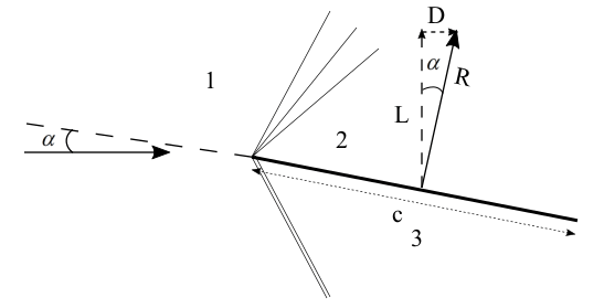 Supersonic flow over a thin flat plate at an angle of attack
From the \(\theta -\beta -M\) relationship, for \(\theta = 8^{\circ}\) and \(M = 3\), \(\beta =25.611^{\circ}\)
Therefore,
\[M_{n1}=M_{1}Sin\beta =3Sin\left ( 25.611^{\circ} \right )=1.297\]
From normal shock properties, for \(M_{n1}=1.297\), \(\frac{p_{3}}{p_{1}}=1.796\)
From isentropic flow properties, for \(M_{1}=3\), \(\left ( \frac{p_{1}}{p_{01}} \right )=0.02722\)
From prandtl-Meyer function for \(M_{1}=3\), \(\nu _{1}=49.76\)
Therefore, \[\nu _{2}=\nu _{1}+\theta =49.76^{\circ}+8^{\circ}=57.76^{\circ}\]
For, \(\nu _{2}=57.76^{\circ}, M_{2}=3.452\)For, \(M_{2}=3.452\), from isentropic flow properties
\[\left ( \frac{p_{2}}{p_{02}} \right )=0.01404\]Therefore,
\[\frac{p_{2}}{p_{1}}=\left ( \frac{p_{2}}{p_{02}} \right )
\left ( \frac{p_{02}}{p_{01}} \right )\left ( \frac{p_{01}}{p_{1}} \right )=\left ( 0.01404 \right )
\left ( 1 \right )\left ( \frac{1}{0.02722} \right )=0.5158\]Total pressure is constant through the expansion wave, \(p_{02}=p_{01}\).
For, a thin flat plate lift per unit span is \(L{}’=\left ( p_{3}-p_{2} \right )\left ( c \right )cos\alpha\)also, \[c_{l}=\frac{L{}’}{q_{1}S}
=\frac{L{}’}{\frac{\gamma }{2}p_{1}M_{1}^{2}c}
=\frac{\left ( p_{3}-p_{2} \right )\left ( c \right ) cos\alpha }{\frac{\gamma }{2}p_{1}M_{1}^{2}c}
=\frac{2}{\gamma M_{1}^{2}}\left ( \frac{p_{3}}{p_{1}}-\frac{p_{2}}{p_{1}} \right )cos\alpha \]
\[\Rightarrow c_{l}=\frac{2}{\left ( 1.4 \right )\left ( 3^{2} \right )}\left ( 1.796-0.5158 \right )cos\left ( 8^{\circ} \right )=0.20123\]For a thin flat plate, drag per unit span is \(D{}’=\left ( p_{3}-p_{2} \right )\left ( c \right )sin\alpha\)
also,
\[c_{d}=\frac{D{}’}{q_{1}S}=\frac{D{}’}{\frac{\gamma }{2}p_{1}M_{1}^{2}c}
=\frac{\left ( p_{3}-p_{2} \right )\left ( c \right ) sin\alpha }{\frac{\gamma }{2}p_{1}M_{1}^{2}c}
=\frac{2}{\gamma M_{1}^{2}}
\left ( \frac{p_{3}}{p_{1}}-\frac{p_{2}}{p_{1}} \right )sin\alpha\]
\[\Rightarrow c_{d}=\frac{2}{\left ( 1.4 \right )\left ( 3^{2} \right )}\left ( 1.796-0.5158 \right )sin\left ( 8^{\circ} \right )=0.02828\]- 1872 views
- 1 answers
- 0 votes