Airfoil Terminology and NACA Series of airfoil Nomenclature.
Define airfoil terminology and NACA series of airfoil nomenclature.

Airfoil terminology
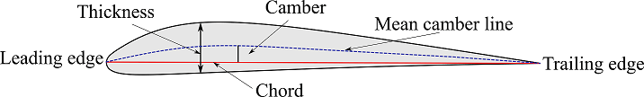
Mean camber line : It is an imaginary line which is halfway between the upper surface and the lower surface of the airfoil. It intersects the chord line at the leading and trailing edge of the airfoil, and it can curve above or below the chord line.
Leading edge :Leading edge is the point which is at the front of airfoil and it is the most forward point of the mean camber line. It has a maximum curvature or minimum radius at front of the airfoil.
Trailing edge: It is the point which is located at the trailing edge of the airfoil and is the most rearward point of the mean camber line. It is also the point of maximum curvature at the rear end of the airfoil.
Chord line : It is a straight line which connects the leading and trailing edge of the airfoil. Chord length or chord is the precise distance from the leading to the trailing edge of the airfoil.
Camber : It is a measure of curvature of the airfoil. it is the maximum distance which is measured perpendicular to the chord line between the mean camber line and the chord line.
Thickness : It varies along the chord of the airfoil.
NACA airfoil nomenclature :
NACA is National Advisory Committee for Aeronautics. It initially developed airfoil system which was numbered, giving a numerical designation to each airfoil. The shape of the airfoil can be described using the of digits which is followed by the word NACA.
NACA 4 digit series : Here, maximum camber, distance of the maximum camber and maximum thickness is defined in terms of the chord ‘c’. For example NACA 2412,
- First digit, 2, describes the maximum camber in hundredth of chord. For this airfoil maximum camber is 0.02c
- Second digit is the distance of the maximum camber from the leading edge of the airfoil in tenths of chord. For the above NACA airfoil, distance of the maximum camber from the leading edge along the chord of the airfoil is 0.4c
- Last two digit gives maximum thickness of the airfoil in hundredths of chord. For the above NACA airfoil, maximum thickness of the airfoil is 0.12c
NACA 5 digit series : Here, the first digit gives the design lift coefficient, second digit gives the location of maximum camber, and last two digit gives the maximum thickness of the airfoil. For example, NACA 23012
- The first digit when multiplied by 3/2, gives the design lift coefficient in tenths. For this airfoil, design lift coefficient is (2 x 3/2=3, 3/10=0.3).
- The next two digit when divided by 2 gives the location of maximum camber from the leading edge of the airfoil in hundredths of chord. For this airfoil, location of maximum camber from the leading edge of the airfoil along chord is (30/2 = 15,= 15c/100=0.15c)
- The last two digit gives the maximum thickness in hundredths of chord . For the above airfoil, maximum thickness of the airfoil is 0.12c
NACA 6 digit series : These are also called laminar flow airfoils. Here, more importance was given to maximise the laminar flow on the airfoil. First digit indicates the series, second digit gives the the location of minimum pressure, third digit gives the design lift coefficient, last two digit gives the maximum thickness . Consider a 6 digit NACA airfoil, NACA 64212
- 6 – It is the NACA series designation.
- Second digit gives the location of minimum pressure in tenths of chord for a basic symmetric thickness distribution at zero lift. For this airfoil, location of minimum pressure is at 0.4c from the leading edge.
- Third digit gives the design lift coefficient in tenths. For this airfoil, design lift coefficient is 0.2
- Last two digit gives the the maximum thickness in hundredths of chord. For the above airfoil maximum thickness of the airfoil is 0.12c
NACA 7 digit series : 7 digit series NACA airfoils had more laminar flow. Here, 7 is the series designation. It indicates location of minimum pressure on upper and lower surface of the airfoil, thickness distribution and mean camber line forms, design lift coefficient, and airfoil maximum thickness. For example NACA 747A315
- Here first digit gives series designation.
- Second digit gives the location of minimum pressure on the upper surface of airfoil in tenths of chord. For this airfoil this is 0.4c
- Third digit gives the location of minimum pressure on lower surface of the airfoil in tenths of chord. For this airfoil it is 0.7c
- The forth one which is a letter gives thickness distribution and mean line forms used. For this airfoil it is ‘A’.
- Fifth digit gives the design lift coefficient in tenths. For this airfoil it is 0.3
- Last digit gives the maximum thickness in hundredths of chord. For this airfoil it is 0.15c
NACA 8 digit series : These were called supercritical airfoils, maximising the laminar flow on upper and lower surface of the airfoil. The naming convention is similar to the 7 digit series, except that that the series begins with 8. For example NACA 835A216
- Here, 8 designates the series
- Location of minimum pressure on upper surface of airfoil is at 0.3c
- Location of minimum pressure on lower surface of the airfoil is 0.5c
- ‘A’ gives the thickness distribution and mean line forms.
- Design lift coefficient for this airfoil is 0.2
- maximum thickness of the airfoil is 0.16c
NACA 1 digit or 16 digit series : 1 digit series is identified with 5 digits. Here, the digits indicates location of minimum pressure, design lift coefficient and maximum thickness. For example NACA 16-123
- Here, the first digit ‘1’ is the series designation.
- Second digit gives the location of minimum pressure in tenths of chord from the leading edge. For this airfoil it is 0.6c
- Third digit gives the design lift coefficient in tenths. For this airfoil it is 0.1
- Last two digit gives the maximum thickness of the airfoil in hundredths of chord. For this airfoil it is 0.23c