331
Points
Questions
27
Answers
67
-
Asked on 21st June 2023 in Others.
ISRO Chandrayaan 3 launch registration is to be live soon from the ISRO official website. Chandrayaan-3 will be launched by GSLV Mark III launch vehicle scheduled on 12th July 2023. Anyone can undergo Isro Chandrayaan 3 launch registration process by visiting their website. By the way all the isro mission registration and isro launch slot registration are done from their website.
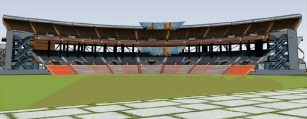
ISRO is one of the foremost space agencies in the world and it has launched many satellites both for India as well as for other countries. Its primary space port is Satish Dhawan Space Center which is located in Sriharikota. In Sriharikota there is a Launch View Gallery made by ISRO for common civilians which has nearly 5000 capacity for spectators to see live views of different launches. Visitors can see live launches with their naked eyes from this gallery. The galleria also possesses large screens where information about the launch vehicle and satellites and various activities about launches are displayed.
So, in order to witness the live launch at the Launch View Gallery at Sriharikota one needs to make their registration from the ISRO official website.
- 792 views
- 1 answers
- 0 votes
-
Asked on 25th January 2022 in Aerodynamics.
Critical Mach number is the free stream Mach number, such that local Mach number on the surface of the body is sonic.
The flow over a cylinder is a two dimensional flow. When there is a flow over a cylinder, the flow moves upwards and downwards.
The flow over a sphere is a three dimensional flow. Therefore when there is a flow over a sphere, it moves upward, downward and also in sideways, left and right.
Therefore, flow over a cylinder has a greater speed than the flow over a sphere. So, to achieve a sonic velocity on the sphere, freestream Mach number is higher than cylinder.
Therefore, critical Mach number of a sphere is higher than cylinder.
- 1142 views
- 1 answers
- 0 votes
-
Asked on 28th December 2021 in Technology.
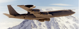
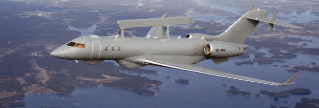
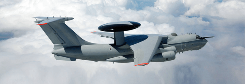
AWACS is Airborne Warning And Control System. It is a long-range radar surveillance system which detects aircraft, ships, vehicles and missiles. The system is mounted on an aircraft. The main antenna is mounted in a circular rotodome. It has a 360 – degree view and can detect aircrafts more than 200 miles away.
AWACS first used pulse-Doppler radar. Present AWACS uses three-dimensional radar that measure azimuth, range and elevation all together.
Airborne early warning and control E-2 Hawkeye uses APY-9 radar which detects fighter stealth aircraft using advanced electronic scanning.
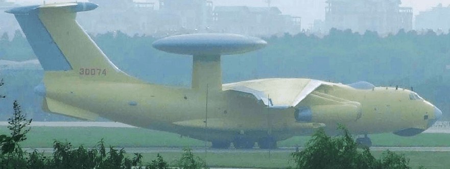
Beriev A-50 and A-50 U “Shmel” uses non-rotating disk radome on the rear fuselage. Beriev A – 100 uses AESA (Active electronically scanned array) array in the radome.
KJ-2000 consists of three phased array radar (PAR) modules which are placed in a triangular configuration in a round radome and gives 360 degree coverage.
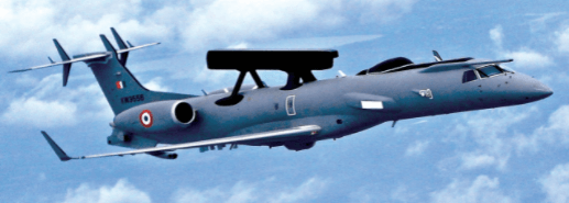
‘Netra’ consists of two radiating planar arrays in an active antenna array unit giving a 240 degree coverage.
GlobalEye uses Erieye radar system which uses active electronically scanned array technology gives a 300 degree coverage and has a instrumental range of 450 km and detection range of 350 km.
EL/W – 2090 uses active electronically scanned array radar and consists of an array transmit / receive modules allowing beam to be electronically steered.
- 1119 views
- 1 answers
- 0 votes
-
Asked on 18th October 2021 in Others.
Jet lag is a human physiological condition that is caused due to quick long-distance trans-meridian (going from east to west or west to east) travel, across multiple time zones.
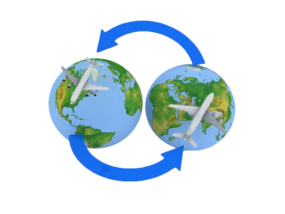 Jet lag occurs due to quick long-distance travel
Jet lag is an issue for frequent travellers, aircraft crew and pilots. Jet lag can cause day time fatigue, sleep disturbances and digestion problems.
Risk of jet lag is more for those who travel more number of time zones, for those who is flying east as when one is flying east he is losing time than for those who fly west, as those who fly west is gaining time.
Earth has nearly 24 time zones which is divided by the longitudes. Each longitude is separated by fifteen degrees, and depending on which direction one travels time moves forward or backward one hour for passing on every fifteen degrees of longitude.
Greenwich meridian is the prime meridian and Greenwich mean time is the world’s time standard. Time zones, tend to follow the boundaries between countries and country’s subdivisions than longitude, because it is more useful to have same time in a particular region, and is a standard time throughout the region.
Jet lag can be prevented by regulating the light exposure and other methods and steps.
- 1209 views
- 1 answers
- 0 votes
-
Asked on 2nd September 2021 in Aerodynamics.
Pressure distribution for a flow over a sphere is given by \left ( C_{p} \right )_{Sphere}= 1 – \frac{9}{4}sin^{2}\thetaFor a cylinder, coefficient of pressure is given as \left ( C_{p} \right )_{Cylinder} = 1 – 4sin^{2}\thetaAt the top of the sphere, \theta = \frac{\pi}{2}
Therefore, coefficient of pressure is \left ( C_{p} \right )_{Sphere}=\left ( 1 – \frac{9}{4}sin^{2}\theta \right )=1-\frac{9}{4}sin^{2}\left ( \frac{\pi}{2} \right )=-1.25In order that there is no deflection of the manometer fluid \left ( C_{p} \right )_{Sphere} should be equal to the \left ( C_{p} \right )_{Cylinder}
Therefore,
\left ( C_{p} \right )_{Sphere}=\left ( C_{p} \right )_{Cylinder}\Rightarrow -1.25=1-4sin^{2}\theta\Rightarrow sin^{2}\theta = \frac{-1.25-1}{-4}=0.5625\Rightarrow sin\theta=\sqrt{0.5625}=0.75\Rightarrow \theta = sin^{-1}\left ( 0.75 \right )=48.59^{\circ}Therefore, tap should be located at 48.59^{\circ} above or below the stagnation point on the cylinder.
- 1201 views
- 1 answers
- 0 votes
-
Asked on 2nd August 2021 in Aerodynamics.
Lift is a force which is generated mostly from wings of an aircraft, moving through air. Lift per unit span is the lift which is produced per unit span of the wing. Span is the distance from one wing tip to the other. Lift per unit span is {L}’=\frac{1}{2}\rho _{\infty}V_{\infty}^{2}c\left ( 1 \right )c_{l}At, an altitude of 2\,km density is 1.0066\,kg/m^3. For an angle of attack of 4^{\circ}, the coefficient of lift for this airfoil is approximately 0.8. Therefore, lift per unit span will be {L}’=\frac{1}{2}\rho _{\infty}V_{\infty}^{2}c\left ( 1 \right )c_{l}\Rightarrow {L}’=\frac{1}{2}\times 1.0066\times \left ( 70 \right )^{2}\times 2\left ( 1 \right )\times 0.8=3945.872\,NCirculation is the line integral of velocity field around a closed curve in a fluid flow. Lift per unit span in a two dimensional flow field is directly proportional to circulation. It is also called Kutta-Joukowski theorem. {L}’=\rho _{\infty}V_{\infty}\tau Therefore, circulation around the airfoil will be {L}’ = \rho _{\infty}V_{\infty}\tau\Rightarrow 3945.872 = 1.0066\times \left ( 70 \right )\times\tau\Rightarrow \tau = 56\,m^{2}/s
- 1324 views
- 1 answers
- 0 votes
-
Asked on 19th July 2021 in Aerodynamics.
From the figure, Lift slope with respect to zero lift angle of attack, a = \frac{dcl}{d\alpha }\Rightarrow a = \frac{c_{l} – c_{l,0}}{\alpha – \alpha _{L=0}}\Rightarrow a = \frac{c_{l} – 0}{\alpha – \alpha _{L=0}}\Rightarrow a = \frac{c_{l}}{\alpha – \alpha _{L=0}}c_{l} = a\left ( \alpha – \alpha _{L=0} \right )Therefore, at an angle of attack of 5^{\circ}, when the airfoil is right-side-up, coefficient of lift isc_{l} = 0.1\left \{ 5^{\circ} – \left ( -3.5^{\circ} \right ) \right \}=0.1\left \{ 8.5^{\circ} \right \}=0.85When, the airfoil is turned upside-down, its zero-lift angle of attack is 3.5^{\circ}. Therefore, coefficient of lift in this condition at 5^{\circ} angle of attack is, c_{l} = 0.1\left ( 5^{\circ} – 3.5^{\circ} \right ) = 0.1\left ( 1.5^{\circ} \right )= 0.15At this condition, to generate the same amount of lift as when the airfoil was right-side-up at 5^{\circ} angle of attack, can be found asc_{l} = a\left ( \alpha – \alpha _{L = 0} \right )\Rightarrow 0.85 = 0.1\left ( \alpha – 3.5^{\circ} \right )\Rightarrow \alpha = 12^{\circ}Therefore, an airfoil can fly upside-down. An airplane can also make an inverted flight, provided its angle of attack is more, in order to generate the same amount lift. In order to increase the angle of attack, an airplane’s nose can be pointed more skyward during the inverted flight.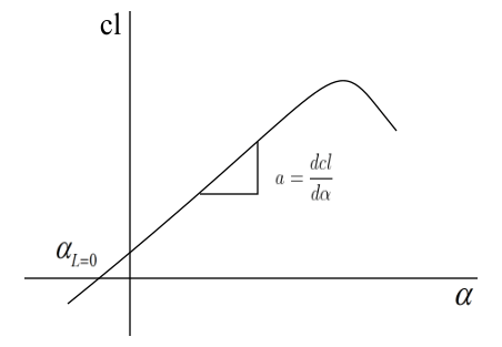 Lift-curve slope for an airfoil
- 2565 views
- 1 answers
- 0 votes
-
Asked on 25th June 2021 in Aeronautics.
Velocity of air in the test section of a low speed open circuit subsonic wind tunnel is given by V_{2} = \sqrt{\frac{2\left ( p_{1} – p_{2} \right )}{\rho \left [ 1 – \left ( \frac{A_{2}}{A_{1}} \right )^{2} \right ]}}Pressure difference, p_{1}-p_{2} is measured by means of a manometer.p_{1}-p_{2}= \gamma \Delta hHere, \gamma = density of mercury * acceleration due to gravity
\Delta h = Difference in heights of the liquid in the manometer between its two side.
Therefore, V_{2}=\sqrt{\frac{2\gamma \Delta h}{\rho \left [ 1-\left ( \frac{A_{2}}{A_{1}} \right )^{2} \right ]}}\gamma = \left ( 1.36 \times 10^{4} \right )\left ( 9.8 \right )=1.33\times 10^{5}N/m^{2}h = 10.5\,cm = 0.105\,m\Rightarrow V_{2} = \sqrt{\frac{2\times \left ( 1.33\times 10^{5} \right )\times 0.105}{1.225\left [ 1-\left ( \frac{1}{10} \right )^{2} \right ]}}=151.8\,m/s
- 1287 views
- 1 answers
- 0 votes
-
Asked on 10th May 2021 in Fluid mechanics.
Velocity field is \vec{V}=3y\hat{i}+4x\hat{j}
Here, \vec{V}=u\hat{i}+v\hat{j}
Acceleration of the fluid particle in the x-direction is given asa_{x}=u\frac{\partial u}{\partial x}+v\frac{\partial u }{\partial y}\Rightarrow a_{x}=3y\frac{\partial }{\partial x}\left ( 3y \right )+4x\frac{\partial }{\partial y}\left ( 3y \right )=\left ( 3y\times 0 \right )+\left ( 4x\times 3 \right )=12xAt point (x,y)=(3,1), acceleration of the fluid particle =12x= 12\times 3= 36\,m/s^{2}- 1368 views
- 1 answers
- 0 votes
-
Asked on 23rd April 2021 in Fluid dynamics.
A streamline is a path traced by imaginary particles moving with the flow. At every point along the path velocity is tangent to the path. Bernoulli’s equation which relates pressure and velocity can be used along the streamline.
Differntial equation of a streamline in a 2-D flow is \frac{dy}{dx}=\frac{v}{u}\Rightarrow \frac{dy}{dx}=\frac{\frac{-x}{x^{3}+y}}{\frac{y}{x^{3}+y}}\Rightarrow \frac{dy}{dx}=\frac{-x}{y}\Rightarrow ydy=-xdx On integrating
\int ydy = -\int xdx\Rightarrow \frac{y^{2}}{2}+c_{1}=\frac{-x^{2}}{2}+c_{2}\Rightarrow \frac{y^{2}}{2}+\frac{x^{2}}{2}=c_{2}-c_{1}\Rightarrow x^{2}+y^{2} = 2\left ( c_{2}-c_{1} \right )\Rightarrow x^{2}+y^{2}=C For a streamline passing through the point (2,6),2^{2}+6^{2}=C\Rightarrow C=40 Therefore, the equation of the streamline passing through the point (2,6) isx^{2}+y^{2}=40This streamline represents a circle with its center at the origin and radius \sqrt{40} units.- 1376 views
- 1 answers
- 0 votes


