624
Points
Questions
72
Answers
119
-
Asked on 3rd March 2021 in Rocket and Space propulsion.
Burnout velocity: It is the velocity of the rocket when propellants stop burning. It is the maximum velocity achieved by a rocket.
Escape velocity : It is the minimum velocity required for a body to escape from a gravitational center of attraction. Kinetic energy of the body is equal to the potential energy and in the absence of any frictional resistance the body will escape from the planet. The escape velocity from earth is 11.2\, km/s. Burnout velocity for a rocket is given by
{V_b} = {g_0}{I_{sp}}\ln \left( {\frac{{{M_i}}}{{{M_f}}}} \right)
\Rightarrow 11.2 \times 1000 = \left( {9.8} \right)\left( {390} \right)\ln \left( {\frac{{{M_i}}}{{{M_f}}}} \right)
\Rightarrow \left( {\frac{{{M_i}}}{{{M_f}}}} \right) = 18.74
Also,
{M_i} = \left( {{M_p} + {M_f}} \right)
\Rightarrow {M_f} = \left( {{M_i} – {M_p}} \right)
\Rightarrow \frac{{{M_i}}}{{{M_f}}} = \frac{{{M_i}}}{{{M_i} – {M_p}}} = \frac{1}{{1 – \left( {\frac{{{M_p}}}{{{M_i}}}} \right)}}
\Rightarrow 18.74 = \frac{1}{{1 – \left( {\frac{{{M_p}}}{{{M_i}}}} \right)}}
\Rightarrow 1 – \left( {\frac{{{M_p}}}{{{M_i}}}} \right) = \frac{1}{{18.74}}
\Rightarrow \frac{{{M_p}}}{{{M_i}}} = 0.947
- 1329 views
- 1 answers
- 0 votes
-
Asked on 19th February 2021 in Flight mechanics.
Static margin is the distance between the center of gravity and neutral point of an aircraft. It is expressed as percentage in terms of mean aerodynamic chord of the wing. Neutral point of an aircraft is the point where aircraft is neutrally stable, when it is disturbed from its trim angle of attack longitudinally.
Neutral point is given as
{h_n} = {h_{ac,wb}} + {V_H}\frac{{{a_t}}}{a}\left( {1 – \frac{{\partial \varepsilon }}{{\partial \alpha }}} \right)
\Rightarrow {h_n} = 0.3 + \left( {0.352} \right)\frac{{0.12}}{{0.085}}\left( {1 – 0.36} \right)
\Rightarrow {h_n} = 0.3 + \left( {0.352} \right)\left( {1.41} \right)\left( {0.64} \right) = 0.618
Static margin, {h_n} – h = 0.618 – 0.38 = 0.238\,{\rm{chord}}\,{\rm{length}}
- 1272 views
- 1 answers
- 0 votes
-
Asked on 10th February 2021 in Flight mechanics.
Airplane’s turn radius is given by
R = \frac{{V_\infty ^2}}{{g\sqrt {{n^2} – 1} }}
and turn rate is \frac{{{V_\infty }}}{R}
Here, n = load factor = (lift/weight)=L/W
Airplane velocity = 403.2\,km/h = 112\,m/s
L = \frac{1}{2}{\rho _\infty }V_\infty ^2S{C_L} = \frac{1}{2} \times 1.225 \times {\left( {112} \right)^2} \times 48 \times 1.3 = 479431.68\,N
Therefore,n = \frac{{479431.68}}{{100000}} = 4.79
Turn radius, R = \frac{{V_\infty ^2}}{{g\sqrt {{{n}^2} – 1} }} = \frac{{{{\left( {112} \right)}^2}}}{{9.8\sqrt {{{\left( {4.79} \right)}^2} – 1} }} = 273.244\,m
Turn rate,\frac{{{V_\infty }}}{R} = \frac{{112}}{{273.244}} = 0.41\,rad/s
- 1202 views
- 1 answers
- 0 votes
-
Asked on 8th February 2021 in Aeronautics.
When airplane is flying at Lift/Drag ratio of maximum , coefficient of drag at zero lift is equal to coefficient of induced drag.
Total\, drag = drag\, at\, zero\, lift + induced\, drag
{C_D} = {C_{D,0}} + {C_{D,i}}
Since (L/D) is here maximum, therefore, coefficient\, of\, drag\, at\, zero\, lift =coefficient\, of\, induced\, drag,
{C_{D,0}} = {C_{D,i}}
Therefore,
{C_D} = 2{C_{D,i}}
{C_{D,i}} = \frac{{C_L^2}}{{\pi eAR}}
L = \frac{1}{2}{\rho _\infty }V_\infty ^2S{C_L}
At, a steady level flight, L=W
\Rightarrow {C_L} = \frac{{2W}}{{{\rho _\infty }V_\infty ^2S}} = \frac{{2 \times 23000}}{{1.225 \times {{\left( {90} \right)}^2} \times 20}} = 0.232
{C_{D,i}} = \frac{{C_L^2}}{{\pi eAR}} = \frac{{{{\left( {0.232} \right)}^2}}}{{\pi \times 0.9 \times 9}} = 0.0021
Therefore,
{C_D} = 2 \times \left( {0.0021} \right) = 0.0041
Total drag,
D = \frac{1}{2} \times {\rho _\infty } \times V_\infty ^2 \times S \times {C_{D}}
\Rightarrow D = \frac{1}{2} \times 1.225 \times {\left( {90} \right)^2} \times 20 \times 0.0041 = 406.823\,N
- 1240 views
- 1 answers
- 0 votes
-
Asked on 4th February 2021 in Flight mechanics.
Induced drag of the airplane, {D_i} = {q_\infty }S{C_{{D_i}}}
Here, {S} = 16\,{m^2}
{\rho _\infty } = 1.225\,kg/{m^3}
{V_\infty } = \left( {\frac{{260 \times 1000}}{{60 \times 60}}} \right) = 72.2\,m/s
{q_\infty } = \frac{1}{2}{\rho _\infty }V_\infty ^2\,
\Rightarrow {q_\infty } = \frac{1}{2} \times \left( {1.225} \right) \times {\left( {72.2} \right)^2} = 3192.86\,N/{m^2}
L = W = 10000 = {q_\infty }S{C_L}
\Rightarrow {C_L} = \frac{{10000}}{{{q_\infty }S}} = \frac{{10000}}{{\left( {3192.86} \right) \times 16}} = 0.1957
{C_{{D_i}}} = \frac{{C_L^2}}{{\pi eAR}} = \frac{{{{\left( {0.1957} \right)}^2}}}{{\pi \times 0.6 \times 7.4}} = 0.002746
Therefore,
{D_i} = {q_\infty }S{C_{{D_i}}} = 3192.86 \times 16 \times 0.002746 = 140.281\,N
- 1007 views
- 1 answers
- 0 votes
-
Asked on 30th December 2020 in Flight mechanics.
Neutral point and static margin come in the context of longitudinal static stability.
Neutral point :
If the position center of gravity is allowed to move, with other things fixed like position of the aerodynamic center, then there will be a position of center of gravity where change in the coefficient of moment about this center of gravity with respect to the absolute angle of attack will be zero, that is \frac{{\partial {C_{M,cg}}}}{{\partial {\alpha _a}}} = 0. There will be also positions of center of gravity when this will be negative or positive. When \frac{{\partial {C_{M,cg}}}}{{\partial {\alpha _a}}} = 0, the position of center of gravity at this point is called neutral point. Neutral point is a fixed point on the aircraft. Center of gravity can move forward and aft of the neutral point. When the center of gravity is forward of the neutral point the aircraft has longitudinal static stability. If it is on the neutral point, it has neutral longitudinal stability, and if it is aft the neutral point it has longitudinal unstability.
Static margin :
It is the distance between the center of gravity and the neutral point of the aircraft, which is expressed with respect to the mean aerodynamic chord of the wing. For longitudinal static stability aircraft’s center of gravity must be forward of the neutral point, that is static margin should be positive. The larger the static margin, the more stable will be the airplane. Therefore, to make an aircraft more responsive to pilot inputs static margin is reduced, that is there will be a low static margin, for such airplanes.
 Neutral point, center of gravity and static margin of an aircraft
- 1191 views
- 1 answers
- 0 votes
-
Asked on 21st December 2020 in Flight mechanics.
Airfoil terminology
Mean camber line : It is an imaginary line which is halfway between the upper surface and the lower surface of the airfoil. It intersects the chord line at the leading and trailing edge of the airfoil, and it can curve above or below the chord line.
Leading edge :Leading edge is the point which is at the front of airfoil and it is the most forward point of the mean camber line. It has a maximum curvature or minimum radius at front of the airfoil.
Trailing edge: It is the point which is located at the trailing edge of the airfoil and is the most rearward point of the mean camber line. It is also the point of maximum curvature at the rear end of the airfoil.
Chord line : It is a straight line which connects the leading and trailing edge of the airfoil. Chord length or chord is the precise distance from the leading to the trailing edge of the airfoil.
Camber : It is a measure of curvature of the airfoil. it is the maximum distance which is measured perpendicular to the chord line between the mean camber line and the chord line.
Thickness : It varies along the chord of the airfoil.
NACA airfoil nomenclature :
NACA is National Advisory Committee for Aeronautics. It initially developed airfoil system which was numbered, giving a numerical designation to each airfoil. The shape of the airfoil can be described using the of digits which is followed by the word NACA.
NACA 4 digit series : Here, maximum camber, distance of the maximum camber and maximum thickness is defined in terms of the chord ‘c’. For example NACA 2412,
- First digit, 2, describes the maximum camber in hundredth of chord. For this airfoil maximum camber is 0.02c
- Second digit is the distance of the maximum camber from the leading edge of the airfoil in tenths of chord. For the above NACA airfoil, distance of the maximum camber from the leading edge along the chord of the airfoil is 0.4c
- Last two digit gives maximum thickness of the airfoil in hundredths of chord. For the above NACA airfoil, maximum thickness of the airfoil is 0.12c
NACA 5 digit series : Here, the first digit gives the design lift coefficient, second digit gives the location of maximum camber, and last two digit gives the maximum thickness of the airfoil. For example, NACA 23012
- The first digit when multiplied by 3/2, gives the design lift coefficient in tenths. For this airfoil, design lift coefficient is (2 x 3/2=3, 3/10=0.3).
- The next two digit when divided by 2 gives the location of maximum camber from the leading edge of the airfoil in hundredths of chord. For this airfoil, location of maximum camber from the leading edge of the airfoil along chord is (30/2 = 15,= 15c/100=0.15c)
- The last two digit gives the maximum thickness in hundredths of chord . For the above airfoil, maximum thickness of the airfoil is 0.12c
NACA 6 digit series : These are also called laminar flow airfoils. Here, more importance was given to maximise the laminar flow on the airfoil. First digit indicates the series, second digit gives the the location of minimum pressure, third digit gives the design lift coefficient, last two digit gives the maximum thickness . Consider a 6 digit NACA airfoil, NACA 64212
- 6 – It is the NACA series designation.
- Second digit gives the location of minimum pressure in tenths of chord for a basic symmetric thickness distribution at zero lift. For this airfoil, location of minimum pressure is at 0.4c from the leading edge.
- Third digit gives the design lift coefficient in tenths. For this airfoil, design lift coefficient is 0.2
- Last two digit gives the the maximum thickness in hundredths of chord. For the above airfoil maximum thickness of the airfoil is 0.12c
NACA 7 digit series : 7 digit series NACA airfoils had more laminar flow. Here, 7 is the series designation. It indicates location of minimum pressure on upper and lower surface of the airfoil, thickness distribution and mean camber line forms, design lift coefficient, and airfoil maximum thickness. For example NACA 747A315
- Here first digit gives series designation.
- Second digit gives the location of minimum pressure on the upper surface of airfoil in tenths of chord. For this airfoil this is 0.4c
- Third digit gives the location of minimum pressure on lower surface of the airfoil in tenths of chord. For this airfoil it is 0.7c
- The forth one which is a letter gives thickness distribution and mean line forms used. For this airfoil it is ‘A’.
- Fifth digit gives the design lift coefficient in tenths. For this airfoil it is 0.3
- Last digit gives the maximum thickness in hundredths of chord. For this airfoil it is 0.15c
NACA 8 digit series : These were called supercritical airfoils, maximising the laminar flow on upper and lower surface of the airfoil. The naming convention is similar to the 7 digit series, except that that the series begins with 8. For example NACA 835A216
- Here, 8 designates the series
- Location of minimum pressure on upper surface of airfoil is at 0.3c
- Location of minimum pressure on lower surface of the airfoil is 0.5c
- ‘A’ gives the thickness distribution and mean line forms.
- Design lift coefficient for this airfoil is 0.2
- maximum thickness of the airfoil is 0.16c
NACA 1 digit or 16 digit series : 1 digit series is identified with 5 digits. Here, the digits indicates location of minimum pressure, design lift coefficient and maximum thickness. For example NACA 16-123
- Here, the first digit ‘1’ is the series designation.
- Second digit gives the location of minimum pressure in tenths of chord from the leading edge. For this airfoil it is 0.6c
- Third digit gives the design lift coefficient in tenths. For this airfoil it is 0.1
- Last two digit gives the maximum thickness of the airfoil in hundredths of chord. For this airfoil it is 0.23c
- 1708 views
- 1 answers
- 0 votes
-
Asked on 9th December 2020 in Flight mechanics.
Rate of climb : Let an airplane is flying at an angle of ‘\theta’ to the horizontal. Lift on the aircraft is perpendicular to the flight velocity and drag is parallel. Weight of the aircraft will be acting perpendicular to the horizontal. Thrust of the aircraft will be aligned to the flight path. So here, thrust on the aircraft will be acting to overcome drag and a component of weight which is W\sin \theta .
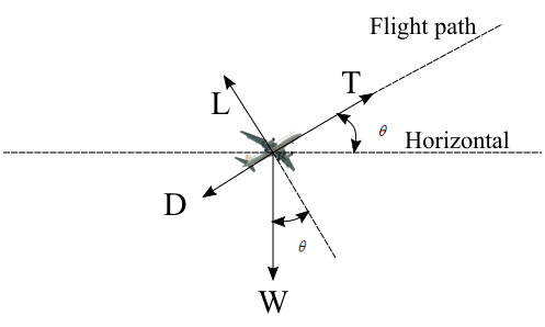 Airplane climbing in atmosphere
T = D + W\sin \theta
Also, here lift will be, L = W\cos \theta
On multiplying both side of thrust equation with {V_\infty },
T{V_\infty } = D{V_\infty } + W{V_\infty }{\sin \theta }
\Rightarrow \frac{{T{V_\infty } – D{V_\infty }}}{W} = {V_\infty }\sin \theta
V_\infty\sin \theta is the rate of climb since it is the vertical velocity of the airplane. Supersonic aircrafts have high accelerated rates of climb. We can calculate the rate of climb of such aircraft by using the energy method.
\frac{{d{H_s}}}{{dt}} = \frac{{dh}}{{dt}} + \frac{V}{g}\frac{{dV}}{{dt}}
Where {H_s} is the specific energy of the aircraft.
Turn rate : Suppose an aircraft makes a level turn with a bank angle \prime \psi \prime . In the level turn weight of the aircraft will be equal to L\cos \psi , that is, W = L\cos \psi There will be a force which will act towards the radius of the circular turn produced by the resultant of lift and weight. This force is F = \sqrt {{L^2} – {W^2}}, also, from Newton’s second law of motion, F = m\frac{{V_\infty ^2}}{R}
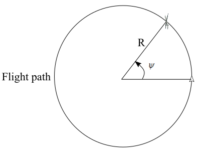 A level turn of an airplane in flight on a horizontal plane
therefore,
m\frac{{V_\infty ^2}}{R} = \sqrt {{L^2} – {W^2}}
\Rightarrow \frac{W}{g}\frac{{V_\infty ^2}}{R} = \sqrt {{L^2} – {W^2}}
\Rightarrow R = \frac{{WV_\infty ^2}}{{g\sqrt {{L^2} – {W^2}} }}
turn rate is \frac{{{V_\infty }}}{R} = \omega , therefore,
\omega = \frac{{g\sqrt {{L^2} – {W^2}} }}{{W{V_\infty }}}
This turn rate is for a level turn on a horizontal plane. For other types of aircraft maneuver force created by the resultant of lift and weight will be different and therefore turn rate will be different.
- 1410 views
- 1 answers
- 0 votes
-
Asked on 27th November 2020 in Flight dynamics.
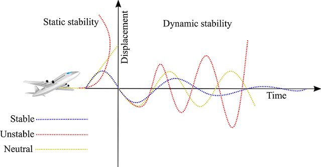
Static stability : If an aircraft in flight is disturbed from its equilibrium state, for example by a gust and the aircraft has its initial tendency to return to its equilibrium state, then the aircraft is having a static stability. Static stability can be divided into statically stable system, statically unstable system and statically neutral system.
Statically stable system (positive static stability) : Aircraft has initial tendency to return to its equilibrium position.
Statically unstable system (Negative static stability) : Aircraft has its initial tendency to move away from its equilibrium position.
Statically neutral system (Neutral static stability) : Aircraft has a tendency to maintains its original disturbed position.
Dynamic stability : When an aircraft is disturbed from its equilibrium position in flight it first go through static stability and later the time history of the aircraft’s motion and attitude makes up the dynamic stability. So dynamic stability is the decay of the amplitude of response over a finite time which has been occurred due to disturbance to reach the equilibrium state.
Dynamic stability can be divided into dynamically stable system, dynamically unstable system, and dynamically neutral system.
Dynamically stable system (Positive dynamic stability ): Aircraft has tendency to return to its equilibrium position through damping of oscillations.
Dynamically unstable system (Negative dynamic stability ) : Aircraft oscillates with increased amplitudes and equilibrium position is never reached.
Dynamically neutral system (Neutral dynamic stability ) : Aircraft maintains uniform oscillations with a constant amplitude.
- 2736 views
- 1 answers
- 0 votes
-
Asked on 11th November 2020 in Aeronautics.
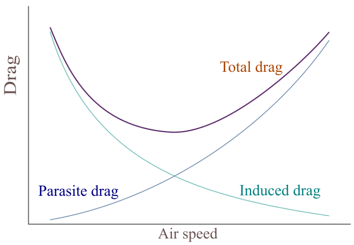
Parasite drag : Induced drag is the drag which results from the lift force which is produced by an aircraft in flight. Parasite drag is the combination of pressure drag and skin friction drag. It is called parasite drag because it is not produced on generation of lift and so parasite in nature. Pressure drag also known as Form drag is caused due to the boundary layer separation which in turn depends on the shape of the object. Skin friction drag is caused due to the skin friction between the object and the moving fluid, that is air, which comes in contact.
Profile drag : Profile drag is the same term for parasite drag when it is used for an aircraft’s wing.
Induced drag : Induced drag which is also called drag due to lift, is produced due to the redirection of airflow which results in generation of vortex. It occurs on lift generating surfaces like aircraft’s wing. The generation of vortex results in downwash. Amount of induced downwash affects the induced drag.
Wave drag : Wave drag is the drag which is produced when there is a formation of shock waves. Shock waves are produced when aircraft is flying at a transonic or supersonic speed. Wave drag is a sudden increase in drag when the aircraft speed crosses critical mach number. Sound barrier is a result of wave drag.
- 1772 views
- 1 answers
- 0 votes

