
- Worldtech
- Earth
- Email is hidden.
513
Points
Questions
117
Answers
70
-
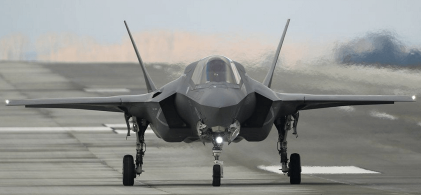
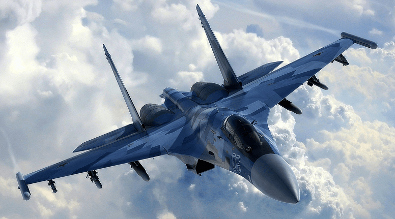
Some of the aircrafts which are used in the Russian-Ukraine war are F-16, F-35, L-39 Albatross, Mig-29, Su-25,An-26, II-76, Su-30, Su-35 and Mig-31.
F-16: It is a single engine fighter aircraft which can perform in all weather conditions and has multirole capability. It can fly at a Mach of 2.05 and has a combat range of 546 km and service ceiling of 50,000 ft.
F-35: It is a single engine all weather stealth multirole combat aircraft. It has three variants, first one is conventional takeoff and landing, second one is short takeoff and vertical landing and third is carrier based launching. It has a maximum speed of Mach 1.6 with a combat range of 1239 km and service ceiling of 50,000 ft.
L-39 Albatross: It is a high performance light attack role aircraft meant to be used for ground attack. It has a maximum speed of 750 km/h and a range of 1100 km with a service ceiling of 36,000 ft.
Mig – 29 : It is a multirole twin engine fighter aircraft. It is capable of performing different operations and has air to surface armaments and precision munitions. It has a Maximum speed of Mach 2.3+ with a combat range of 900 km and service ceiling 59,000 ft.
Su-25: It is a twin engine single seat subsonic jet aircraft. The aircraft has a metal cantilever wing with moderate sweep and high aspect ratio and equipped with high lift devices. It has a maximum speed of Mach 0.79 with a combat range of 750 km and service ceiling of 23,000 ft.
An-26: It is a twin engine turbo-prop civilian and military transport aircraft. It has a cruise speed of 440 km/h with a range of 2500 km and service ceiling of 24,600 ft.
II-76: It is a fixed-wing multipurpose four engine turbofan aircraft initially designed to carry heavy machinery in remote areas. It has also been used for air-refueling and command center. It has a maximum speed of Mach 0.82 and a range of 4400 km and a service ceiling of 43,000 ft.
Su-30: It is a twin engine all weather multirole fighter aircraft which is supermaneuverable and can carry out air to air and air to surface missions. It has a maximum speed of Mach 2 and a range of 3000 km with a service ceiling of 56,800 ft.
Su-35: It is a twin engine single seat supermaneuverable aircraft which is an upgraded version of su-27. It has a maximum speed of Mach 2.25 at altitude and Mach 1.13 at sea level with a combat range of 1600 km and service ceiling of 59,000 ft.
Mig-31: It is a supersonic interceptor aircraft and is an upgraded version of Mig-25. It has a maximum speed of Mach 2.83 and a combat range of 720 km, with a service ceiling of 82,000 ft.
- 1198 views
- 1 answers
- 0 votes
-
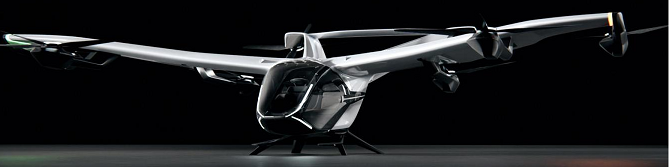
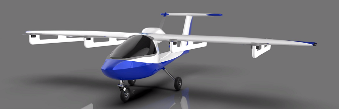
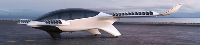
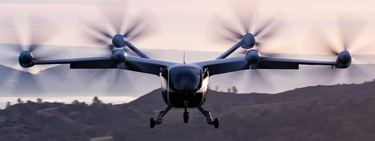
Urban air mobility is a system of urban transportation in which people move by air. It is a concept of intracity passenger transport. Urban air mobility includes small drones, electric aircraft and automated air traffic management that along with transport of passengers also include cargo and logistics mission.
Urban air mobility has VTOL( Vertical take-off and landing) capabilities, which can take off and land vertically in a small area. Most of the designs are electric and in order to reduce noise multiple rotors are used.
All-electric concepts makes a perfectly suited zero-emission flight operations. Urban air mobility requires air traffic management for new aerial vehicles, air taxis and drones for a safer sky and sharing of skies.
Unmanned traffic management is required for rapid growth of unmanned aerial vehicles. It is also required for safe practice, understanding current airspace usage and analysing risk.
Some urban air mobility concepts:
- 1946 views
- 1 answers
- 0 votes
-
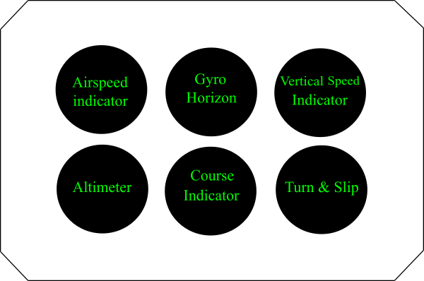
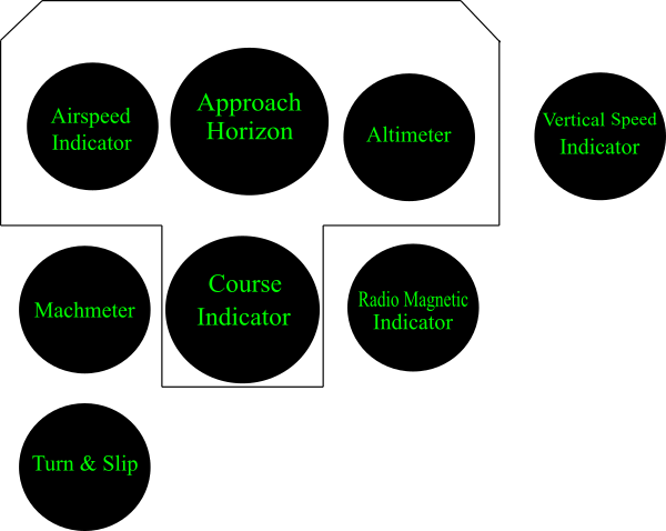
Six flight instruments, which are used in aircraft’s flight are airspeed indicator, altimeter, gyro horizon, direction indicator, vertical speed indicator and turn-and-bank indicator. The “basic six” layout of grouping the instruments is shown below. With the development and coming of new aircraft instruments the position is in “basic T” layout. It is in standard locations so that flight related information can be gathered.
Airspeed indicator, altimeter and vertical speed indicator uses the pitot-static system. The pitot-static system senses the total pressure which is created by the forward motion of the aircraft and the static pressure of the surrounding atmosphere and measure it in terms of aircraft speed, altitude and rate of change of altitude, by means of instruments airspeed indicator, altimeter and vertical speed indicator.
Altimeter measures the altitude which is above sea level. Altimeter uses android barometer. The barometer measures altitude by measuring the surrounding air pressure. Above the earth’s surface as altitude increases, the air pressure decreases, because of lowering of density of air.
A simple barometric altimeter consists of a sealed metal chamber, spring and pointer. When there is a decrease in air pressure chamber expands and when there is a increase in pressure the chamber contracts. This makes the spring to bend which leads to move the pointer.
Now, altimeters are made which uses global positioning system. It uses signals from different satellites to determine the altitude. There are also radar and laser altimeter. It sends a radio or laser signal towards the surface of earth and time taken by the signal to bounce back, is used to measure the altitude.
Airspeed indicator indicates the airspeed of an aircraft in terms of kilometres per hour, knots, miles per hour or meters per second. Airspeed indicator
measures the pressure difference between static pressures detected from pressure probe and total pressure of the pitot tube.Machmeter: Machmeter shows the ratio of airspeed and the speed of sound.
Vertical speed indicators: These indicates the rate of climb of an aircraft by indicating the rate of change in altitude, using pitot-static flight instruments. Altitude change is measured from the change of static pressure only.
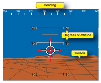
Gyro horizon: It indicates the pitch and bank attitude of an aircraft, which is relative to the vertical. Gyro horizon uses displacement gyroscope. There are also vacuum-driven gyro horizon and electric gyro horizon.
Turn-and-Bank indicator: It uses gyroscope and a magnetic compass, and is primarily used on small aircrafts. Turn rates is indicated by the rate gyroscope which is using gyroscopic precession. Mechanical methods for bank indication uses a gravity weight and pointer mechanism and other method as a ball in a glass tube which is curved and is filled with liquid.
For the heading indication a direct reading were magnetic compass, used in early days. Now a days directional gyroscope , remote-reading compass systems and flight director systems are used.
Tachometer: Speed of aircraft engines are measured by tachometer. For reciprocating engines the speed of crank-shaft is measured. For turboprop and turbojet engines rotational speed of compressor shaft is measured. This measurement gives a useful indication of thrust produced by the engine.
Flight director system: It consists of an approach horizon and a course deviation indicator. Flight director attitude indicator represents aircraft attitude and instrument landing system information which is in a 3-dimensional display. Attitude is indicated by a stationary delta-shaped symbol that represents the aircraft and bank and pitch commands which is displayed by two pointers or by command bars or horizon bar. Command bars move up and down to show a change in pitch or rotate clockwise and anti-clockwise for change in bank attitude.
Course deviation indicator: Aircraft is represented by a fixed symbol at the center which indicates the position and heading of the aircraft.
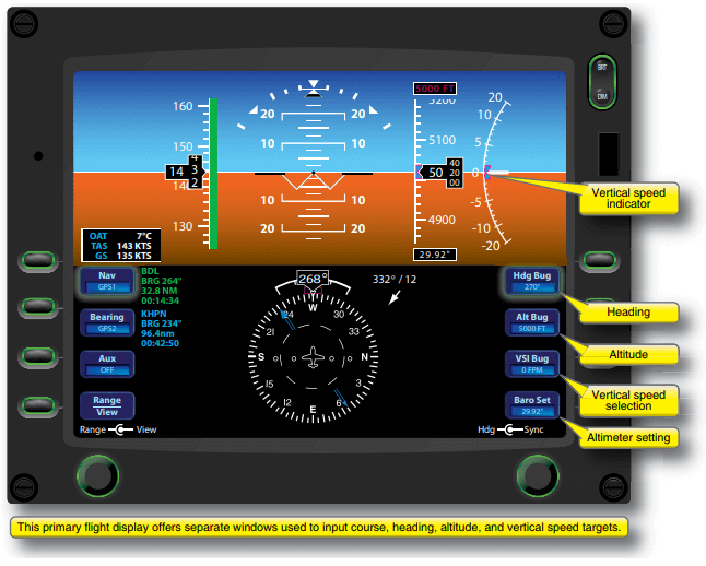 Primary flight display present in modern aircrafts
Other instruments are Mach warning system, Instantaneous vertical speed indicator, Turn co-ordinator, Temperature indicator, Engine-cylinder-head temperature indicator, Turbine-engine gas temperature indicator, Pressure indicator, Refueling control panel, Engine power and control instrument.
- 1731 views
- 1 answers
- 0 votes
-
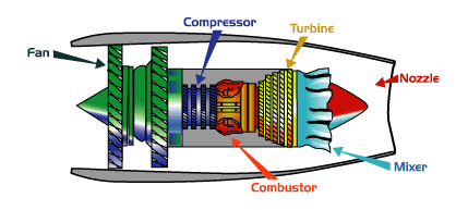
Jet engines: Jet engines are used to propel the aircraft forward, with huge amount of thrust. A jet engine consists of fan/ Diffuser, compressor, combustor, turbine, nozzle.
Diffuser: Diffuser which is present in a turbojet engine is deaccelerating the flow at inlet. In a turbofan engine a fan is present at inlet to accelerate a large mass of air. Thrust produced by a turbofan engine is a sum of thrust produced by fan blades and jet from the nozzle.
Compressor: Compressor compresses the inflow air which results in an increase in air pressure. A compressor is made up of fans with many blades which is attached to a shaft. The high pressure squeezed air is passed into the combustion chamber.
Combustor: Compressed air from compressor is passed into the combustion chamber where fuel is sprayed from the nozzle. The mixture of air and fuel burns and produce a high temperature and high-energy airflow. There is a expansion of the gas.
Turbine: Airflow from combustor enters the turbine, which causes the blades of turbine to rotate. Turbines are on shaft connecting to compressor and fan at the inlet, which turns the blades of the compressor and spin the fan.
Nozzle: Airflow after passing from turbine exhausts from the nozzle producing the thrust. The high-energy of the air-flow is lost after passing the turbine and and there is also addition of cooler air which is bypassed in the engine core, this leads to generate a force when exiting the nozzle.
The Jet engines has made particular increase in aircraft speed in the recent years. Jet engines has made supersonic flights possible. The invention and development of jet engine provided the thrust necessary for everyday supersonic flights. Jet engines are used by almost all large commercial transports and military combat aircrafts at present.
The power available from jet engine is given as product of thrust available and aircraft velocity. Thrust available for the jet engine is nearly constant with the velocity. Therefore, power available also varies linearly with velocity.
The fuel which is consumed by a jet engine physically depends on the thrust produced by the engine. When an airplane is flying at minimum thrust required, the jet airplane has a maximum endurance.
At maximum endurance, jet airplane is flying at a velocity where \(C_{L}/C_{D}\) is maximum and maximum range for jet airplane occurs when it is flying at a velocity where \(C_{L}^{1/2}/C_{D}\) is maximum. Here, \(C_{L}\) is the coefficient of lift and \(C_{D}\) is coefficient of drag.
Range of jet airplane also depends on density of atmosphere. Range is increased if density is low. But at extremely high altitudes, ordinary turbojet engine has a decrease in performance. Range of a jet engine is lowest at sea level and it increases with altitude up to a point.
The cruising altitudes for a subsonic commercial jet transport aircraft is \(30,000\) to \(40,000\, ft\) and for a supersonic jet transport aircraft it is \(50,000\) to \(60,000\, ft\).
So, jet engine is a device which takes in air at a freestream velocity at inlet, there is combustion with fuel inside the duct and then blasts of hot mixture of air and combustion products at the backend at a very large velocity.
So, jet engine creates a change in the momentum of the gas by increasing the velocity of the small mass of intake air.
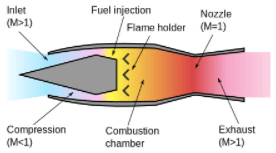
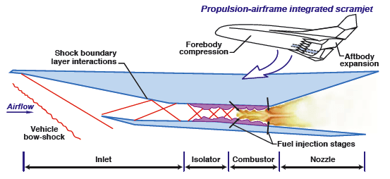
Ramjet engine: A ramjet engine does not have any rotating machinery like fans or propellers like in a turbojet. It is simply a straight through duct. In a ramjet engine air at a high velocity is inducted through the inlet, which is decelerated in the diffuser and after that burned by the injecting fuel, which later blast out the exhaust nozzle at a very high velocity. Ramjet engine is the best choice for future hypersonic vehicles.
At a high Mach number combustion temperature for a turbojet engine is increased. But there is a material limitation for the turbine blades as at a high temperature, it will melt. This high temperature material properties limit the turbojet engine to lower to moderate supersonic velocities.
However, a ramjet does not have any moving parts and turbines, so there is no high temperature material limitation.
There can be a higher combustion chamber temperature and therefore a higher supersonic flight velocities. A ramjet engine can have a Mach number above \(3\) or \(4\).
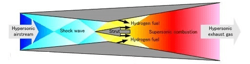
At a higher Mach number like above Mach \(6\), there is a large increase in temperature that will lead to fail ramjet structurally. Also, if the temperature of air entering the combustion chamber is high, it will decompose rather burn, when fuel is injected in the combustion chamber.
This has led to supersonic combustion ramjet which is called scramjet. In scramjet the diffuser, decelerates the airflow but flow is still supersonic when entering the combustor. Fuel is injected in the combustion chamber where supersonic combustion takes place. Here, static temperature is low, and the material limitation and decomposition of air problem evade.
So, a scramjet engine can make the hypersonic flight possible. Scramjet powered flights are envisioned for Mach numbers of at least \(15\).
In order to start and run a ramjet engine, it has to be in motion. A ramjet engine must have enough flight speed to start the engine, and to achieve this a ramjet-powered vehicle is launched with rockets or a second engine of different type to push it to enough flight speed.
In a hypersonic vehicle having a scramjet engine the airflow is passing through one or more shock-wave systems from the leading portion of the vehicle. Therefore, it is required to tailor the aerodynamics of this inflow air to have the most efficient engine performance.
- 1782 views
- 1 answers
- 0 votes
-
Induced drag is created due to downwash. Downwash is produced by the wing-tip vortices during flight. Aspect ratio of the wing is, \[AR=\frac{b^{2}}{S}=\frac{\left ( 10 \right )^{2}}{15}=6.67\]
At, standard sea level density of air is \(1.225\,kg/m^{3}\)
Velocity of airplane is \(50\,m/s\)
Dynamic pressure, \[q_{\infty} = \frac{1}{2}\rho _{\infty}V_{\infty}^{2}=\frac{1}{2}\times1.225\times\left ( 50 \right )^{2}=1531.25\,N/m^{2}\]
Lift slop of the airfoil of the wing is \(0.102 \,per\,degree = 5.8442\,per\,radian\)
Lift produced by the wing is, \[L=\frac{1}{2}\rho _{\infty}V_{\infty}^{2}SC_{L}=\rho _{\infty}SC_{L}\]\[\Rightarrow C_{L}=\frac{L}{\rho _{\infty}S}\]
L = Weight of the airplane = \(1000\times9.8 = 9800\,N\)
Therefore, \[C_{L} = \frac{9800}{1531.25\times15}=0.427\]
Lift slope of the wing will be, \[a = \frac{a_{0}}{1 + \frac{a_{0}}{\pi AR}\left ( 1+\tau \right ) }=\frac{5.8442}{1+\frac{5.8442}{\pi\left ( 6.67 \right )}\left ( 1+0.1 \right )}=4.472\,per\,radian = 0.0781\,per\,degree\]
Also, Coefficient of lift is given as \[C_{L}=a\left ( \alpha -\alpha _{L=0} \right )\Rightarrow 0.427=0.0781\left ( \alpha -\left ( -2.5^{\circ} \right ) \right )\Rightarrow \alpha = 2.97\,degree\]
Induced drag is given as \[D_{i}=q_{\infty}SC_{D,i}\]\[ C_{D,i}=\frac{C_{L}^{2}}{\pi e AR}=\frac{\left ( 0.427 \right )^{2}}{\pi \left ( 0.6 \right )\left ( 6.67 \right )}=0.0145\]
Therefore, \(D_{i} = \left ( 1531.25 \right )\left ( 15 \right )\left ( 0.0145 \right ) = 333.05\,N\)
- 1456 views
- 1 answers
- 0 votes
-
Aerodynamic center is a point on the airfoil for which the aerodynamically generated moment is independent of the angle of attack or the coefficient of lift. Aerodynamic center is at \(\frac{1}{4}\) chord from the leading edge for most of the low speed airfoils. For supersonic airfoils aerodynamic center lies nearer at \(\frac{1}{2}\) chord length. Location of the aerodynamic center as a fraction of the chord length is given as \[x_{ac}=-\frac{m_{0}}{a_{0}}+0.25\]\(m_{0}\) = Slope of the moment coefficient curve, \[m_{0}=\frac{-0.040-\left ( -0.050 \right )}{4^{\circ}-\left ( -6^{\circ} \right )}=0.001\textrm{ per degree}\] \(a_{0}\) = Slope of the lift coefficient curve, \[a_{0} = \frac{0.70-\left ( -0.35 \right )}{4^{\circ}-\left ( 6^{\circ} \right )} = 0.105 \textrm{ per degree}\]Therefore, aerodynamic center lies at,\[x_{ac} = -\frac{m_{0}}{a_{0}} + 0.25\]\[\Rightarrow x_{ac} = -\frac{0.001}{0.105} + 0.25 = 0.240 \textrm{ chord length}\]
- 1896 views
- 1 answers
- 0 votes
-
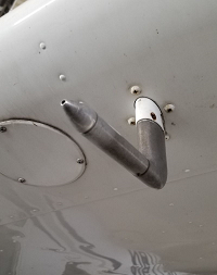
Pitot tube: It is a flow measurement device which is used to measure the fluid flow velocity. It is used to determine the velocity of an aircraft.
Velocity is determined using the Bernoulli’s equation.Total pressure = static pressure + dynamic pressure \[p_{0}=p_{s} + \frac{1}{2}\rho V^{2}\]\[\Rightarrow V = \sqrt{\frac{2\left ( p_{0} – p_{s} \right )}{\rho }}\]Here,\[p_{0} = 1.09 \times 10^{5}\,N/m^{2}\]\[p_{s}=1.01 \times 10^{5}\, N/m^{2}\]\[\rho = 1.225\, kg/m^{3}\]Therefore,\[V=\sqrt{\frac{2\left ( 1.09\times 10^{5}-1.01\times 10^{5} \right )}{1.225}}=114.3\,m/s\]
- 1696 views
- 1 answers
- 0 votes
-
Velocity field,\(V=u\hat{i}+v\hat{i}+w\hat{k}\)
Here, \(V=5xy\hat{i}+8txz\hat{j}+xz\hat{k}\)
Angular velocity of a fluid particle in a fluid flow is \(\omega = \omega _{x}\hat{i}+\omega _{y}\hat{j}+\omega _{z}\hat{k}\)
\[\omega =\frac{1}{2}\left [ \left ( \frac{\partial w }{\partial y}-\frac{\partial v}{\partial z} \right )\hat{i}+
\left ( \frac{\partial u}{\partial z}-\frac{\partial w}{\partial x} \right )\hat{j}+
\left ( \frac{\partial v}{\partial x}-\frac{\partial u}{\partial y} \right )\hat{k} \right ]\]
Angular velocity about the z-axis
\[\omega_{z}=\frac{1}{2}\left ( \frac{\partial v}{\partial x}-\frac{\partial u}{\partial y} \right )=\frac{1}{2}\left ( \frac{\partial }{\partial x}\left ( 8txz \right )-\frac{\partial }{\partial y}\left ( 5xy \right ) \right )=\frac{1}{2}\left ( 8tz-5x \right )\]
At point \((2,3,5)\) and \(t=3\), angular velocity is \[\omega _{z}=\frac{1}{2}\left ( 8tz-5x \right )=\frac{1}{2}\left ( \left ( 8\times 3\times 5 \right )-\left ( 5\times 2 \right ) \right )=\frac{1}{2}\left ( 120-10 \right )=55\]
Vorticity of fluid particle in a fluid flow is \(\xi =2\omega \)
\[\Rightarrow \xi = \left ( \frac{\partial w}{\partial y}-\frac{\partial v}{\partial z} \right )\hat{i}
+\left ( \frac{\partial u}{\partial z}-\frac{\partial w}{\partial x} \right )\hat{j}
+\left ( \frac{\partial v}{\partial x}-\frac{\partial u}{\partial y} \right )\hat{k}\]\[\Rightarrow \xi = \left ( \frac{\partial }{\partial y}\left ( xz \right )
-\frac{\partial }{\partial z} \left ( 8txz \right )\right )\hat{i}
+\left ( \frac{\partial }{\partial z}\left ( 5xy \right )
-\frac{\partial }{\partial x}\left ( xz \right ) \right )\hat{j}+\left ( \frac{\partial }{\partial x}\left ( 8txz \right )
-\frac{\partial }{\partial y}\left ( 5xy \right ) \right )\hat{k}\]\[\Rightarrow \xi =\left ( 0-8tx \right )\hat{i}+\left ( 0-z \right )\hat{j}+\left ( 8tz -5x \right )\hat{k}\]
At point \((2,3,5)\) and at \(t=3\),
\[\xi =\left ( -8\times 3\times 2 \right )\hat{i}+\left ( -5 \right )\hat{j}
+\left ( \left ( 8\times 3\times 5 \right )
-\left ( 5\times 2 \right ) \right )\hat{k}\]\[\Rightarrow \xi =-48\hat{i}-5\hat{j}+110\hat{k}\]
Acceleration of a fluid particle in a fluid flow is
\[a=\frac{\partial v}{\partial t}+u\frac{\partial v}{\partial x}
+v\frac{\partial v}{\partial y}+w\frac{\partial v }{\partial z}\]\[\Rightarrow a=\frac{\partial }{\partial t}\left ( 5xy\hat{i} +8txz\hat{j}+xz\hat{k}\right )+\left ( 5xy \right )
\frac{\partial }{\partial x}\left ( 5xy\hat{i}+ 8txz\hat{j}+xz\hat{k}\right )+\]\[\left ( 8txz \right )\frac{\partial }
{\partial y}\left ( 5xy\hat{i} +8txz\hat{j}+xz\hat{k}\right )+\left ( xz \right )\frac{\partial }
{\partial z}\left ( 5xy\hat{i} +8txz\hat{j}+xz\hat{k}\right )\]\[\Rightarrow a=8xz\hat{j}+\left [ \left ( 5xy \right )\left ( 5y\hat{i}+8tz\hat{j}+z\hat{k} \right ) \right ]+\left [ \left ( 8txz \right )\left ( 5x\hat{i} \right ) \right ]+\left ( xz \right )\left [ \left ( 8tx\hat{j}+x\hat{k} \right ) \right ]\]
At point \((2,3,5)\) and at \(t=3\),
\[a=\left ( 8\times\times 2\times 5 \right )\hat{j}+\left [ \left ( 5\times 2\times 3 \right ) \left ( 5\times 3 \right )\hat{i}+
\left ( 8\times 3\times 5 \right )\hat{j}+5\hat{k}\right ]+\]\[\left [ \left ( 8\times 3\times 2\times 5 \right )\left ( 5\times 2 \right )\hat{i} \right ]+
\left [ \left ( 2\times 5 \right )\left ( 8\times 3\times 2 \right )\hat{j}+2\hat{k} \right ]\]\[\Rightarrow a=80\hat{j}+450\hat{i}+120\hat{j}+5\hat{k}+2400\hat{i}+480\hat{j}+2\hat{k}\]\[\Rightarrow a = 2850\hat{i}+680\hat{j}+7\hat{k}\]- 1566 views
- 1 answers
- 0 votes
-
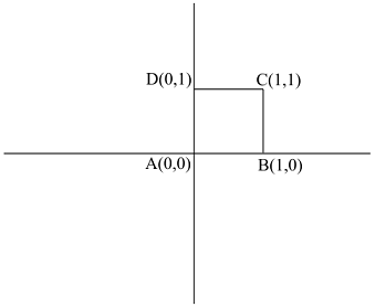 Circulation around a rectangular contour
The closed contour is a square and its corner are at \(A(0,0), B(1,0), C(1,1), D(0,1)\).
Circulation is given by \[ \Gamma =\int _{ABCD}udx + vdy\]
\[\Rightarrow\Gamma = \int_{A}^{B}udx + \int_{B}^{C}vdy+\int_{C}^{D}udx+\int_{D}^{A}vdy\]
\[=\int_{0}^{1}\left ( x^{2}+y \right )dx +
\int_{0}^{1}\left ( x^{3}+2y \right )dy+\int_{1}^{0}\left ( x^{2}+ y \right )dx + \int_{1}^{0}\left ( x^{3}+2y \right )dy\] In the first integral, \(y=0\), in second integral \(x=1\), in the third integral, \(y=1\) and in the fourth integral \(x=0\).
\[=\int_{0}^{1}\left ( x^{2} \right )dx +
\int_{0}^{1}\left ( 1 + 2y \right )dy + \int_{1}^{0}\left ( x^{2} + 1 \right )dx + \int_{1}^{0}\left ( 2y \right ) dy\]
\[=\left | \frac{x^{3}}{3} \right |_{0}^{1}+\left | y+
\frac{2y^{2}}{2} \right |_{0}^{1}+\left | \frac{x^{3}}{3} + x \right |_{1}^{0}+\left | \frac{2y^{2}}{2} \right |_{1}^{0}\]
\[=\left [ \frac{1}{3} \right ]+\left [ 1+1 \right ]+\left [ -\frac{1}{3}-1 \right ]+\left [ -1 \right ]=0\]- 1744 views
- 1 answers
- 0 votes
-
In an isentropic flow total pressure is constant.
For an isentropic flow,\[\left ( \frac{p_{0}}{p} \right )=\left ( \frac{T_{0}}{T} \right )^{\frac{\gamma }{\gamma -1}}\]\[\Rightarrow T= T_{0}\left ( \frac{p}{p_{0}} \right )^{\frac{\gamma-1 }{\gamma}}\]\[\Rightarrow T= 600\left ( \frac{1}{11} \right )^{\frac{0.4}{1.4}}=302.42\,K\]Also,\[p=\rho RT\]\[\Rightarrow \rho =\frac{p}{RT}=\frac{1.01\times 10^{5}}{\left ( 287 \right )\left ( 302.42 \right )}=1.164\,kg/m^{3}\]
- 1564 views
- 1 answers
- 0 votes