
- Worldtech
- Earth
- Email is hidden.
513
Points
Questions
117
Answers
70
-
Mass flow rate at the throat which is at sonic condition is \[\dot{m}=\rho ^{*}A^{*}V^{*}\]Specific gas constant \[R=\frac{8314}{16}=519.6\,J/\left ( kg\,K \right )\]At sonic condition, \[\frac{\rho ^{*}}{\rho _{0}}=\left ( \frac{2}{\gamma +1} \right )^{\frac{1}{\gamma -1}}
=\left ( \frac{2}{1.2+1} \right )^{\left ( \frac{1}{1.2-1} \right )}=0.621\]\[\rho ^{*}=\left ( \frac{\rho ^{*}}{\rho _{0}} \right )\rho _{0}=0.621\rho _{0}=0.621\left ( \frac{p_{0}}{RT_{0}} \right )
=0.621\left ( \frac{p_{0}}{519.6\times 3500K} \right )=3.415\times 10^{-7}p_{0}\]At sonic condition,
\[\left ( \frac{T^{*}}{T_{0}} \right )=\left ( \frac{2}{\gamma +1} \right )=\left ( \frac{2}{1.2 +1} \right )=0.9091\]\[T^{*}=\left ( \frac{T^{*}}{T_{0}} \right )T_{0}=0.9091\times 3500=3181.85\,K\]Also, at throat\[V^{*}=a^{*}=\sqrt{\gamma RT^{*}}=\sqrt{\left ( 1.2 \right )\left ( 519.6 \right )\left ( 3500 \right )}=1477.27\,m/s\]Since, \(\dot{m}=\rho ^{*}A^{*}V^{*}\)\[\Rightarrow 300=\left ( 3.415\times 10^{-7} p_{0}\right )\times \left ( 0.25 \right )\times 1477.27\]\[\Rightarrow p_{0}=2.3787\times 10^{6}\,N/m^{2}\]- 1678 views
- 1 answers
- 0 votes
-
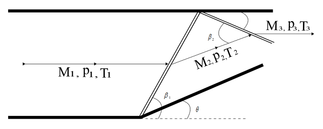
Wave angle \(\beta _{1}\) can be obtained from the \(\theta\, -\beta\, – M\) diagram. For, deflection angle of \(20^{^{\circ}}\) and Mach number \(M_{1}\) of \(3.4\), \(\beta _{1}=35^{^{\circ}}\)
Therefore,
\[M_{n1}=M_{1}Sin\beta _{1} = 3.4Sin35^{^{\circ}}=1.95\]
For a normal shock wave for \(M_{n1}=1.95\),
\(\frac{p_{2}}{p_{1}}=4.27\), \(\frac{T_{2}}{T_{1}}=1.6473\) and \(M_{n2}=0.586\)
Therefore,
\[M_{2}=\frac{M_{n2}}{Sin\left ( \beta _{1}-\theta \right )}=\frac{0.586}{Sin\left ( 35^{^{\circ}}-20^{^{\circ}} \right )}=2.26\]
For the reflected shock, from \(\theta -\beta\, – M\) diagram, for \(M_{2}=2.26\) and \(\theta = 20^{^{\circ}}\) , wave angle, \(\beta _{2}=46.75^{^{\circ}}\)
Therefore,
\[M_{n2}=M_{2}Sin\beta _{2} = 2.26Sin46.75^{^{\circ}}=1.65\]
For a normal shock wave, for \(M_{n2}=1.56\)
\(\frac{p_{3}}{p_{2}}=3.001\), \(\frac{T_{3}}{T_{2}}=1.423\) and \(M_{n3}=0.654\)
Therefore,
\[M_{3}=\frac{M_{n3}}{Sin\left ( \beta _{2}-\theta \right )}=\frac{0.654}{Sin\left ( 46.75^{\circ}-20^{\circ} \right )}=1.453\]
and \[p_{3}=\left ( \frac{p_{3}}{p_{2}} \right )\left ( \frac{p_{2}}{p_{1}} \right )\left ( p_{1} \right )=\left ( 3.001 \right )\left ( 4.27 \right )\left ( 1 \right )=12.814\,atm\]
and \[T_{3}=\left ( \frac{T_{3}}{T_{2}} \right )\left ( \frac{T_{2}}{T_{1}} \right )\left ( T_{1} \right )=\left ( 1.423 \right )\left ( 1.6473 \right )\left ( 300\,K \right )=703.23\,K\]
Angle made by the reflected shock wave with the upper wall = \(\beta _{2}-\theta =46.75^{\circ}-20^{\circ}=26.75^{\circ}\)
- 1668 views
- 1 answers
- 0 votes
-
Entropy is a measure of molecular disorder or randomness in any system. Useful work is obtained when there is a ordered molecular motion, so entropy of a system is the measure of thermal energy per unit temperature which is unavailable for doing any useful work. Entropy change across a normal shock is given by
\[\frac{{{p_{02}}}}{{{p_{01}}}} = {e^{ – \left( {{s_2} – {s_1}} \right)/R}}\]
\[ \Rightarrow \frac{{{p_{02}}}}{{{p_{01}}}} = {e^{ – \left( {220} \right)/287}} = 0.46\]
Therefore, from normal shock properties table, for, \(\frac{{{p_{02}}}}{{{p_{01}}}} = 0.46\), upstream Mach number \(M_1\), is around \(2.6\).
- 1662 views
- 1 answers
- 0 votes
-
Burnout velocity of a rocket is the velocity of the rocket at the time when there is depletion of the fuel and oxidant or the propellants. It is the maximum velocity achieved by a rocket. Burnout velocity is given as:
\[{V_b} = {g_0}{I_{sp}}\ln \left( {\frac{{{M_i}}}{{{M_f}}}} \right)\]
\[ \Rightarrow {V_b} = \left( {9.8} \right)\left( {390} \right)\ln \left( 7 \right) = 7437.27\,m/s\]
- 1596 views
- 1 answers
- 0 votes
-
Thrust produced by a turbojet engine is given as
\[T = \dot m\left( {{V_e} – {V_\infty }} \right) + \left( {{P_e} – {P_\infty }} \right){A_e}\]
At an altitude of \(10 000\,m\) ,
\[{P_\infty } = 2.65 \times {10^4}\,N/{m^2}\]
\[{\rho _\infty } = 0.41351\,kg/{m^3}\]
\[{V_\infty } = \,900\,km/h = \,250\,m/s\]
\[\dot m = {\rho _\infty }{A_i}{V_\infty } = \,0.41351 \times 0.9 \times 250 = 93.04\,kg/s\]
Therefore , Thrust
\[T = 93.04\left( {500 – 250} \right) + \left( {32500 – 26500} \right)1.3 = 31060 \,N\]
- 1506 views
- 1 answers
- 0 votes
-
For a wing-body combination of an airplane
\[{C_{M,cg}} = {C_{M,ac}} + {C_L}\left( {h – {h_{ac}}} \right)\]
Here, \(h – {h_{ac}}\) is difference of distances of center of gravity and aerodynamic center in terms of fraction of chord length from the wing’s leading edge .
Therefore,
\[0.006 = – 0.015 + {C_L}\left( {0.035} \right)\]
\[ \Rightarrow {C_L} = \left( {0.006 + 0.015} \right)/0.035 = 0.6\]
- 1412 views
- 1 answers
- 0 votes
-
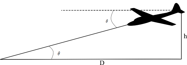
Aircraft starts to glide at an altitude of \(1500\,m\).
From the figure,
\[\tan \theta = \frac{h}{D} \Rightarrow D = \frac{h}{{\tan \theta }}\]
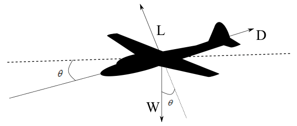
For the unaccelerated glide, in equilibrium \(L = W\cos \theta \), \(D = W\sin \theta \),
\[ \Rightarrow \left( {\frac{L}{D}} \right) = \frac{{W\cos \theta }}{{W\sin \theta }} = \left( {\frac{1}{{\tan \theta }}} \right)\]
On putting the values , to calculate the distance
\[D = \frac{h}{{\tan \theta }} = h\left( {\frac{L}{D}} \right) = 1500 \times 8 = 12000\,m\]
- 1720 views
- 1 answers
- 0 votes
-
Lift on an airplane is \[L = \frac{1}{2}{\rho _\infty }V_\infty ^2S{C_L}\]
Since, in a steady level flight , Lift = Weight, Therefore, \[L = W = \frac{1}{2}{\rho _\infty }V_\infty ^2S{C_L}\]
Stalling speed is when the coefficient of lift is maximum. Therefore, \[W = \frac{1}{2}{\rho _\infty }V_{Stall}^2S{C_{L,\max }} \Rightarrow V_{Stall}^2 = \frac{{2W}}{{{\rho _\infty }S{C_{L,\max }}}}\]
\[ \Rightarrow {V_{Stall}} = \sqrt {\frac{{2W}}{{{\rho _\infty }S{C_{L,\max }}}}} = \sqrt {\frac{{2 \times 8000}}{{1.225 \times 17 \times 2.2}}} = 18.69\,m/s\]
- 1638 views
- 1 answers
- 0 votes
-
An aircraft in flight, produces wing tip vortices. Low pressure is created on the top surface and a high pressure is created on the bottom surface. This difference in pressure leads to air flow at the wing tips creating a circulatory motion which trails down stream of the wing. These are called vortex.
These wing tip vortices creates downwash which results in induced drag.
Induced drag can be calculated as \[{D_i} = L\sin {\alpha _i}\] where \(L\) is the lift. Since induced angle of attack \({\alpha _i}\) is small. Therefore,\[{D_i} = L{\alpha _i}\]
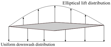
For an elliptical wing, lift per unit span varies elliptically along its span, and has a uniform downwash distribution. Induced angle of attack for the elliptical wing, from incompressible flow theory is \[{\alpha _i} = \frac{{{C_L}}}{{\pi AR}}\]
Therefore induced drag will be\[{D_i} = L{\alpha _i} = L \times \frac{{{C_L}}}{{\pi AR}}\]
and coefficient of induced drag will be \[{C_{D,i}} = \frac{{C_L^2}}{{\pi AR}}\]
For all general wings a span efficiency factor, \(e\) is defined such that \[{C_{D,i}} = \frac{{C_L^2}}{{\pi eAR}}\]
and \(e <= 1\). Span efficiency factor, \( e \), comes from the calculation of coefficient of induced drag from the Prandtl’s classical lifting line theory. For all general planform wings \(e\) is less than 1. For an elliptical wing, \(e=1\). Therefore, induced drag is minimum for an elliptical wing planform. For a typical subsonic airplane, \(e\) is between 0.85 to 0.95, therefore for such airplane aspect ratio is increased to minimise the induced drag.
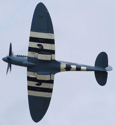 An elliptical wing planform aircraft
An elliptical wing planform is expensive to make, for such a tapered wing with an approximate elliptical lift distribution is made. Induced drag coefficient for an tapered wing with straight leading and trailing edges has a minimum value and are easier to produce.
- 1839 views
- 1 answers
- 0 votes
-
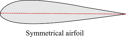
Symmetric airfoil: An airfoil is a cross-sectional shape of a wing. A symmetric airfoil has same shape on both sides of the centerline which is chord. Mean camber line of an airfoil is the line that is halfway between the upper surface and lower surface of the airfoil. So, the mean camber line and chord line of a symmetric airfoil will be the same. Hence, camber of a symmetric airfoil will be zero. A symmetric airfoil in an airflow at zero degree angle of attack does not produce any lift. Also, the aerodynamic center and center of pressure lies at the same point on the airfoil. Symmetric airfoils are used in helicopter rotors and in the wings of an aerobatic aircraft. Aerobatic aircraft need to generate lift in spinning or when the aircraft is flying inverted. Horizontal and vertical tails of an aircraft have a symmetric airfoil.
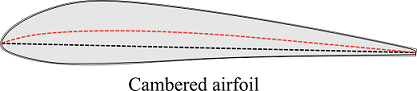
Asymmetric airfoil / Cambered airfoil : An airfoil which has a camber is called an asymmetric or a cambered airfoil. Camber of an airfoil is a measure of airfoil curvature. For a cambered airfoil, the mean camber line and the chord line is different. An airfoil can have a positive camber or a negative camber. Generally, an airfoil has a positive camber which means the mean camber line is above the chord line. An airfoil having a positive camber is more convex. A cambered airfoil can produce lift even at zero degree angle of attack in an airflow. Aerodynamic center and center of pressure does not lie at the same point in a cambered airfoil. Cambered airfoil produces more lift and less drag than a symmetrical airfoil, given at the same density, airspeed, and angle of attack. Therefore, all aircraft generally uses an cambered airfoil. Aircraft designers can vary the camber along the wing span to give different lift characteristics which may be used to improve stall condition or stall recovery. Cambered airfoils are also used in a propeller blade.
- 6113 views
- 1 answers
- 0 votes