
- Worldtech
- Earth
- Email is hidden.
513
Points
Questions
117
Answers
70
-
Bernoulli’s equation tells us about the relationship between pressure and velocity for an inviscid and incompressible flow. The equation is \[p + \frac{1}{2}\rho {V^2} = {\text{constant}}\] The equation states that static pressure + dynamic pressure = total pressure. Here, the constant represents the total pressure of the flow.
To derive Bernoulli’s equation consider \( ‘x ‘\) component of momentum equation of an inviscid flow with no body forces acting on the flow, the equation is \[\rho \frac{{Du}}{{Dt}} = – \frac{{\partial p}}{{\partial x}}\]
This is \[\rho \frac{{\partial u}}{{\partial t}} + \rho u\frac{{\partial u}}{{\partial x}} + \rho v\frac{{\partial u}}{{\partial y}} + \rho w\frac{{\partial u}}{{\partial z}} = – \frac{{\partial p}}{{\partial x}}\]
The flow is steady, therefore \(\frac{{\partial u}}{{\partial t}}=0\)
and the equation now becomes \[u\frac{{\partial u}}{{\partial x}} + v\frac{{\partial u}}{{\partial y}} + w\frac{{\partial u}}{{\partial z}} = – \frac{1}{\rho }\frac{{\partial p}}{{\partial x}}\]
On multiplying both side with \(‘ dx ‘\) , \[u\frac{{\partial u}}{{\partial x}}dx + v\frac{{\partial u}}{{\partial y}}dx + w\frac{{\partial u}}{{\partial z}}dx = – \frac{1}{\rho }\frac{{\partial p}}{{\partial x}}dx\]
For a streamline 3D flow \[udz – wdx = 0\]
\[vdx – udy = 0\]
On substituting it in above equation , it will become \[u\left( {\frac{{\partial u}}{{\partial x}}dx + \frac{{\partial u}}{{\partial y}}dy + \frac{{\partial u}}{{\partial z}}dz} \right) = – \frac{1}{\rho }\frac{{\partial p}}{{\partial x}}dx\]
Since, \[du = \left( {\frac{{\partial u}}{{\partial x}}dx + \frac{{\partial u}}{{\partial y}}dy + \frac{{\partial u}}{{\partial z}}dz} \right)\]
Therefore, the above equation will become, \[udu = – \frac{1}{\rho }\frac{{\partial p}}{{\partial x}}dx\]
\[ \Rightarrow \frac{1}{2}d\left( {{u^2}} \right) = – \frac{1}{\rho }\frac{{\partial p}}{{\partial x}}dx\]
Similarly for \(y\) and \(z\) component of momentum equation for the inviscid flow with no body forces,
\[\frac{1}{2}d\left( {{v^2}} \right) = – \frac{1}{\rho }\frac{{\partial p}}{{\partial y}}dy\]
and
\[\frac{1}{2}d\left( {{w^2}} \right) = – \frac{1}{\rho }\frac{{\partial p}}{{\partial z}}dz\]
On adding these \(x,y,z\) components of equations
\[\frac{1}{2}d\left( {{u^2} + {v^2} + {w^2}} \right) = – \frac{1}{\rho }\left( {\frac{{\partial p}}{{\partial x}}dx + \frac{{\partial p}}{{\partial y}}dy + \frac{{\partial p}}{{\partial z}}dz} \right)\]
\[{u^2} + {v^2} + {w^2} = {V^2}\]
and also
\[\frac{{\partial p}}{{\partial x}}dx + \frac{{\partial p}}{{\partial y}}dy + \frac{{\partial p}}{{\partial z}}dz = dp\]
Therefore, the equation will become,
\[\frac{1}{2}d\left( {{V^2}} \right) = – \frac{{dp}}{\rho }\]
\[ \Rightarrow dp = – \rho VdV\]
For a streamline flow, with density being constant on integrating the above equation between two points of the flow,
\[\int\limits_{{p_1}}^{{p_2}} {dp = – \rho \int\limits_{{V_1}}^{{V_2}} {VdV} } \]
The equation becomes \[{p_2} – {p_1} = – \rho \left( {\frac{{V_2^2}}{2} – \frac{{V_1^2}}{2}} \right)\]
\[ \Rightarrow {p_1} + \frac{1}{2}\rho V_1^2 = {p_2} + \frac{1}{2}\rho V_2^2\]
This is the Bernoulli’s equation. If a flow is irrotational, then
\[p + \frac{1}{2}\rho {V^2} = {\text{constant}}\]
From, the above equation it can be deduced that if density is constant, then if velocity increases then the pressure decreases and if velocity decreases then pressure increases in the flow. This is also called Bernoulli’s theorem. Bernoulli’s equation can be used to derive the lift and drag force for a low speed airfoil where the flow is incompressible and density is constant. Surface of the airfoil, has a streamline flow, and velocity varies along this airfoil, therefore Bernoulli’s equation can be used to find the pressure by integrating over the entire surface of the airfoil.
Bernoulli’s equation is also used in pitot-static tube which is used in aircraft’s instrument to provide information about aircraft’s speed.
- 1941 views
- 1 answers
- 0 votes
-
During takeoff and landing an airplane it is at its lowest flight velocity. Stalling speed of an aircraft is the minimum speed at which it can fly in a straight and level flight. At stalling speed, an aircraft is flying at an angle of attack which produces maximum coefficient of lift.
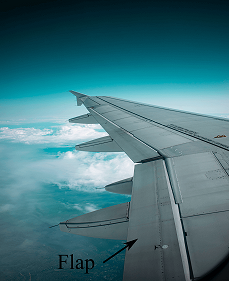
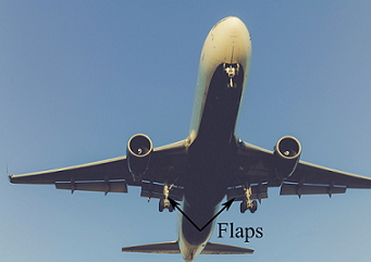 An airplane during takeoff with flaps down
So, if we want to have a decrease in stall velocity, we need to increase more coefficient of lift of the airfoil. A wing with a given airfoil shape has a fixed maximum coefficient of lift, which is dependent on the nature of flow physics over the airfoil. In order to increase the coefficient of lift, artificial high lifting devices are used. Flaps are the high lift devices that are located at the trailing edge of the wing.
Flaps increase the lift coefficient when it is deflected downwards. Flaps increase the camber as well as the chord of the airfoil, resulting in an increase in coefficient of lift.
The following sequence is in increasing order of maximum coefficient of lift produced by flaps and addition of other high lift devices. Plain flap < split flap <airfoil with a leading edge slat < airfoil with a single-slotted flap < airfoil with a double slotted flap < airfoil with a double slotted flap and a slat < airfoil with a boundary-layer suction at top of the airfoil.
So flaps increase the maximum lift coefficient of an airfoil, which can be used to reduce the take-off and landing distance.
- 1760 views
- 1 answers
- 0 votes
-
Instrument landing system : The International Telecommunication Union defines it as a radio navigation system which provides aircraft with horizontal and vertical guidance just before and during landing and, at certain fixed points, indicates the distance to the reference point of landing.
Instrument landing system is used for lateral and vertical guidance for a precision approach on a runway. It consists of the following components,
-
- Localizer
- Glide path
- Markers
- DME
- Approach lighting system
- Runway visual range
Localizer: Localizer sends a VHF carrier signal of 90 Hz and 150 Hz sideband signals which the aircraft instrument determines as an left and right of the centerline of the runway.
Glide path: Glide path is used to give vertical guidance. It is located 750 to 1250 feet down the runway threshold and 400 to 600 ft off the runway centre line. Glide slope sends a UHF carrier signal with 90 Hz and 150 Hz sideband frequencies which aircraft instruments determine as above or below the desired glide path of the aircraft.
Markers: Markers are outer and middle markers. Marker helps the pilot to make a positive position fix on the localizer. It has a carrier frequency of 75 Hz. When the transmission from the marker beacon is received by the aircraft instrument a tone is audible to the pilot and an indicator is activated.
DME: it is distance measuring equipment and is used to give a slant distance with respect to the touch down point of the aircraft.
Approach lighting system : It consists of approaching light system, sequenced flashing light, touchdown zone lights and centre line lights.
Runway visual range: It is the distance at when a pilot of an aircraft can see surface markings on the runway. It determines operational visual aids of the airport.
- 1642 views
- 1 answers
- 0 votes
-
-
ICAO : ICAO is the International Civil aviation Organisation. It works on a sustainable development of civil aviation for safe and secure international air transport through the cooperation of its member states. Its headquarters is located in Montreal, Canada. There are 193 ICAO member states at present. ICAO is a standards organization. ICAO has standardized some functions of the airline industry like Aeronautical Message Handling System. It has also defined International Standard Atmosphere. ICAO has its own airport and airline code system.
IATA : IATA is the International air transport association. It is a trade association of the airline companies of the world which sets up technical standards, and also helps to formulate industry policy. Its headquarter is located in Montreal, Canada. IATA gives international airlines a mechanism to fix prices. IATA has its focus area on safety and has its IATA Operational Safety Audit. It also helps the airline by simplifying the airline businesses. IATA has its own airline and airport code system.
- 2115 views
- 1 answers
- 0 votes
-
When an aircraft is in flight it rotates about the center of gravity. A three dimensional coordinate system can be defined, through the center of gravity, whose axis are perpendicular to each other.These three perpendicular axis are termed as yaw axis, pitch axis and roll axis.
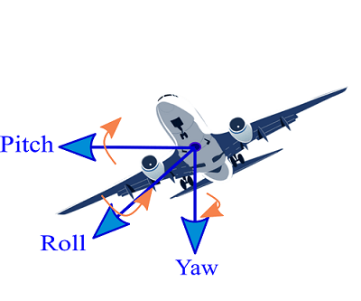 Yaw, pitch and roll axis of an aircraft
The axis which is perpendicular to the plane of the wings and is directed downward with origin at the aircraft’s center of gravity is the yaw axis. Rotation of the aircraft around this vertical axis is called yaw. Here, nose of the aircraft is left to right and vice-versa. Yaw motion is done through rudder of the aircraft.
The axis which is perpendicular to the yaw axis and is parallel to the plane of the wings is the pitch axis. It is passed through the center of gravity and is directed towards the wright wing. A pitch motion is the up and down movement of the nose of the aircraft, with respect to this axis. Pitch motion of the aircraft is controlled by the rudder.
The axis which is perpendicular to both the yaw and pitch axis and is origin is at the center of gravity of the aircraft directed towards the nose is the roll axis. Roll is the tilting of the aircraft’s wing up and down. Rolling is created by the use of ailerons of the aircraft’s wing.
- 2076 views
- 1 answers
- 0 votes
-
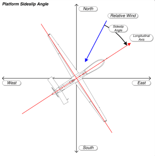
A sideslip is a sideways movement towards inside a turn by an aircraft relative to the incoming airflow. Side slip can be initiated by a point or it can be unintentional. An uncoordinated turn in which a pilot does not give a sufficient rudder input can crate a sideslip.
A pilot can create sideslip in order to have a large increase in the rate of descent and in case of crosswind during landing to maintain the runway centre line by putting aileron input in one direction with rudder input in the opposite direction.
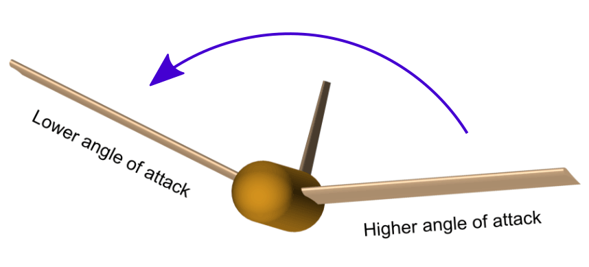
An aircraft’s wing is dihedral when the wing is in upward angle and it is anhedral when it is in downward angle. Dihedral increases lateral stability in bank because lower wings fly at a higher angle of attack than the higher wing which is at a lower angle angle of attack.
When aircraft rolls dihedral create a restoring moment and increases the stability of the aircraft.
- 1871 views
- 1 answers
- 0 votes
-
1 g is equal to the gravitational acceleration on earth which is equal to 9.8 \(m/{s^2}\). G force is the vector sum of non-gravitational and non-electromagnetic forces. G force is resistance as a result of mechanical forces to the object. When an object is in free-fall under the influence of gravitation, the condition is known as zero-g. G force is experienced by the aircraft pilots.
Pilot sustain g forces along the axis of the spine. There is a variation in the blood pressure along the length of the body. There is a limit to the maximum g forces which can be tolerated by a human body. A positive vertical g force can cause a blackout, G-LOC, or even death if g force is not quickly reduced.
- 1937 views
- 1 answers
- 0 votes
-
Aerodynamic flutter is caused due to aeroelastic effects and lightweight and large aerodynamic loads. Flutter is an uncontained vibration. In an aircraft, this can occur on wings, horizontal tail, and in control surfaces. Flutter occurs due to the interactions between the aerodynamic, elastic and inertial forces. Flutter can be classified into two types hard flutter and soft flutter. In hard flutter, there is a sudden decrease in vibration to zero, whereas in soft flutter vibration decreases slowly and gradually.
Structures like wings and also bridges and chimneys which are exposed to aerodynamic forces are designed in such a way that it can avoid flutter. Changing the mass distribution of aircraft or stiffness of a component can induce flutter. This starts with less violent but it can be more violent and can be uncontrollable which can lead to damage or destruction of aircraft. In a propeller aircraft aerodynamic and inertial effects of the rotating propeller and stiffness of the supporting nacelle structure causes propeller whirl flutter.- 2064 views
- 1 answers
- 0 votes
-
Aspect ratio:
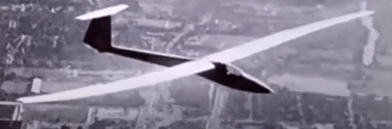
Aspect ratio of a wing is defined as the square of the wingspan divided by the wing area. For a rectangular wing, it is defined as the ratio of wingspan to the ratio of the wing chord. High aspect ratio wings have a long span like high-performance gliders. Low aspect ratio wings have short spans or thick chords. Induced drag of an aircraft is inversely proportional to aspect ratio. A higher aspect ratio wing has a lower induced drag than a lower aspect ratio wing. Lift to drag ratio of an aircraft increases with aspect ratio which improves the fuel economy of the aircraft.
Aspect ratio of a wing can be defined by \[AR = \frac{{{b^2}}}{S}\]
where ‘b’ is the wing span and ‘S’ is the projected wing area.
However, there are limitations to a higher aspect ratio. There are structural limitations. A long wing will require a higher structural-design because of a higher bending stress. A low aspect ratio wing is more maneuverable and has a higher roll angular acceleration than a high aspect ratio wing. High aspect ratio wing has a higher parasitic drag.
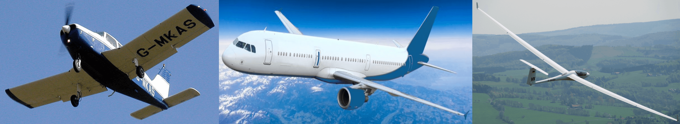 Low aspect ratio,moderate aspect ratio and high aspect ratio wing aircrafts
- 1728 views
- 1 answers
- 0 votes
-
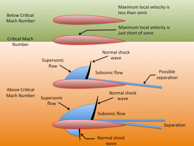
When there is an airflow over the airfoil, the gas expands around the top surface of the airfoil near the leading edge which rapidly increases the velocity and Mach number of the airflow. There are regions on the surface of the airfoil where the local Mach number is greater than the freestream Mach number. As the freestream Mach number increases, the peak local Mach number on the surface also increases. On increasing further the freestream Mach number, peak local Mach number on the surface of the airfoil can be 1.0, which is a locally sonic flow on the surface of the airfoil.
Therefore, flow can be locally sonic or higher, even if the freestream Mach number is subsonic. Therefore, a critical Mach number is a free-stream Mach number at which sonic flow is first achieved somewhere on the airfoil surface. For a thin airfoil, the expansion over the top surface is mild, there is only a slight increase in velocity. For a medium thickness, the flow expansion over the leading edge for the medium airfoil is stronger, the velocity increase to a large value. Since flow separation is stronger, sonic conditions are obtained sooner on the surface of the airfoil. Therefore, the critical Mach number of medium-thickness airfoil is less than the critical Mach number of a thin airfoil and thick airfoil has lower critical Mach number than thin airfoil and medium-thickness airfoil.
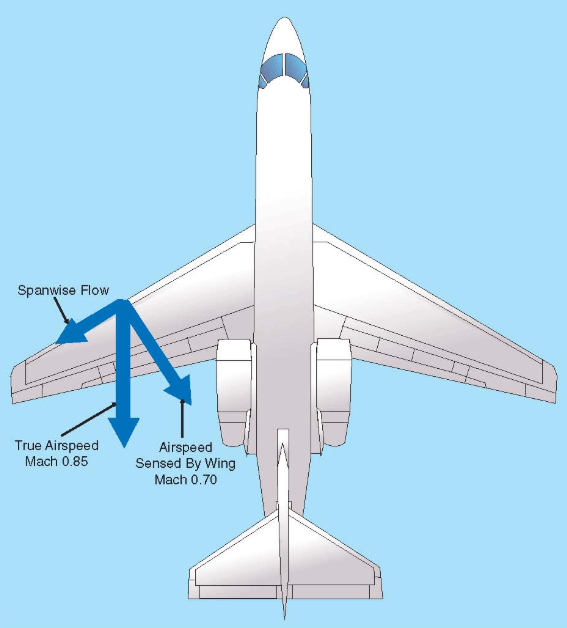
Swept wings have a greater critical Mach number than the straight wing.
- 2671 views
- 1 answers
- 0 votes