513
Points
Questions
117
Answers
70
-
Asked on 3rd July 2020 in Flight mechanics.
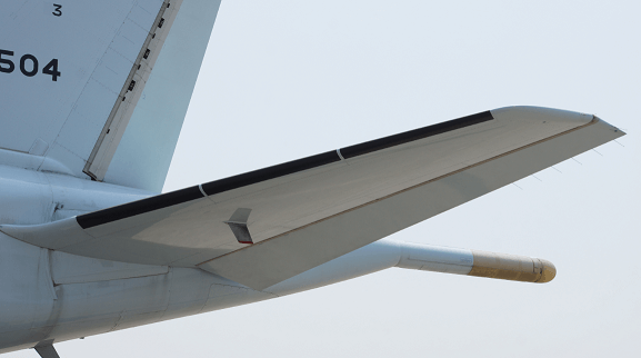
Horizontal stabilizer and elevator are located at the rear of the fuselage of most of the aircraft. A horizontal stabilizer is a fixed-wing section that provides stability to the aircraft and thus aircraft flies straight. It stabilizes the nose of the aircraft from pitching up and down. It helps the aircraft to maintain a longitudinal balance.
A horizontal stabilizer generates varying amounts of forces because of the movement of the elevator which is attached by hinges at the rear of the horizontal stabilizer. This varying force controls the pitching motion of the aircraft. The deflection of the elevator changes the angle of attack of the wing, which in turn changes the lift produced by the wing.
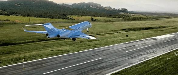
Therefore, the elevator can be used for climbing and diving of aircraft. It makes the aircraft to climb by bringing the nose of the aircraft up during take off. Also, elevators helps to make the aircraft a tighter turn. The deflection of the elevator changes the elevator shape of the horizontal stabilizer with greater downward deflection, increasing the lift. The lift force is generated at the center of pressure of the horizontal stabilizer.
Some aircraft have a horizontal surface forward of the center of gravity of the aircraft at the front end, for pitching stability and control. This surface is called a canard.- 1518 views
- 1 answers
- 0 votes
-
Asked on 30th June 2020 in Aeronautics.
Airport’s capacity is determined by several key factors, which includes size and the number of runways. Length of the runway is determined by aircraft type, ground surface type, longitudinal slope, altitude and the climate. It is also determined by the type of aircraft that will operate at the airport most frequently. Since there are different types of aircraft operating in different situations, there is a specification for every aircraft requiring a specific runway length.
For ideal design conditions, there will be a 0.0 % longitudinal slope of the runway, but geomorphological constraints can make the construction of the runway having a significant slope. The direction of the winds and keeping the above factors, whether the slope is positive or negative, will affect the length of the runway.
The friction coefficient between the runway and aircraft’s wheels directly affects take-offs and landings, and so determines the runway length. Runways are made of asphalt, cement, grass, earth, or compact snow. Altitude also affects the runway length. Runway length at altitude is higher than the sea level. As altitude increases, air density decreases, this decreases the thrust produced by the aircraft engine. Also, low air density results in less lift from the aircraft wings.
For climatic conditions, temperature is one of the important factors, which defines the length of the runway. Temperature affects the air density and higher temperature results in a lower air density.
- 1204 views
- 1 answers
- 0 votes
-
Asked on 11th June 2020 in Aeronautics.
A supersonic aircraft is an aircraft that is able to fly faster than the speed of sound, which is Mach number 1. Based on speed an aircraft can be categorized as subsonic aircraft, transonic aircraft, supersonic aircraft, and hypersonic aircraft.
Subsonic aircraft are those which fly at a speed less than the speed of sound. Transonic aircraft are those which are flying near the speed of sound. It is around Mach number 0.8 to 1.2. Hypersonic aircraft are those which can fly above Mach number 5.
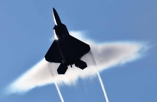
Supersonic aircraft of higher Mach number develops shock waves and expansion waves where local air densities, temperature, and pressure varies due to compressibility effects. These aircraft have specialized inlet systems that bring high speed air into the engine. Supersonic aircraft have swept wings in order to reduce drag. Since at higher Mach number, greater than 2.5 there is generation of heat due to frictional heating of air with the airframe, aluminium is not used for the structure. Some other metals which have good high temperature characteristics like titanium can be used.
Supersonic aircraft which fly Mach number less than 2.5, there is a lower frictional heating of the airframe by the air, here aluminium can be used for the structure. Type of engines used for supersonic aircraft are turbojet engines, or low bypass turbofans engines. Ramjet engines can also be used, but it needs to be started at a higher flying velocity.
The first supersonic aircraft was the Bell X-1 experimental plane. Supersonic airplanes at present find their large usage in military fighter aircraft. For commercial aircraft needs to be environmental and economically viable. Concord was the first supersonic commercial aircraft. Boom supersonic, Aerion supersonic and Spike aerospace are some of the aerospace companies which are working on future supersonic passenger aircraft.
- 1321 views
- 1 answers
- 0 votes
-
Asked on 27th May 2020 in Astronomy.
Earth is a planet of the solar system which is third from the sun and is the only one that supports life. Earth is estimated to be formed nearly 4.5 billion years ago. It has an abundance of water and its chemical composition and environment favors life. Seventy percent of the earth’s surface is covered with water.
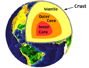
Earth has a radius of 6371 kilometers. It is composed of different layers inner core, outer core, mantle and crust. The inner core is about 1221 kilometers in radius and is made of iron and nickel metals. It is solid. The inner core is surrounded by an outer core which is about 2300 kilometers thick. It is a fluid layer and is made up of iron and nickel.
Above the outer core is the mantle. It is about 2900 kilometers thick and has a viscous mixture of molten silicate rock. Outermost layer is the earth’s crust. It is about 30 kilometers deep on land and 5 kilometers deep from the seafloor. Earth’s crust is abundant with solid rocks and minerals which are in silicates. Lithosphere that consists of the crust and the upper part of the mantle is broken into tectonic plates which moves allowing heat to escape into the atmosphere.
Earth’s land surface is covered with plains, mountains, valleys, rivers and lakes. Its atmosphere consists of gases mostly nitrogen and oxygen. Other gases such as argon and carbon dioxide are in a very small percentage.
- 1321 views
- 1 answers
- 0 votes
-
Asked on 9th November 2019 in Aerodynamics.
From the results of thin airfoil theory c_{l}=2\pi\alpha=2\pi\left ( \frac{1.5}{57.3} \right )=0.164\;\mathrm{radians}
c_{m,le}=-\frac{c_{l}}{4}=-\frac{0.164}{4}=-0.041
- 2232 views
- 1 answers
- 0 votes
-
Asked on 5th November 2019 in Aerodynamics.
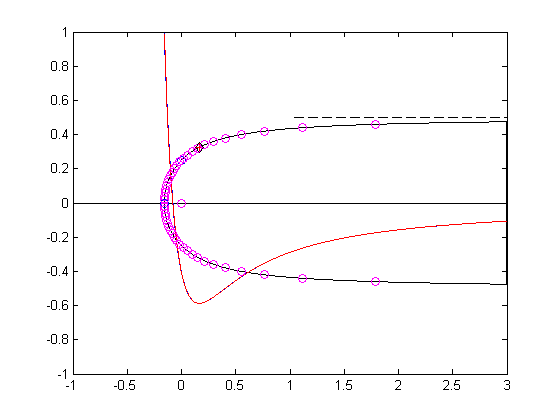
The Rankine nose or Rankine leading edge is an example of flow around the leading edge of a symmetric aerodynamic body which is symmetric about the x-axis of coordinate system.This flow can be obtained by adding a uniform flow and a source flow at the origin.The velocity potential and stream function of this flow is
\phi=U_{\infty}x+\frac{m}{4\pi}ln\left ( x^{2}+y^{2} \right )\;,\;\psi=U_{\infty}y+\frac{m}{2\pi}tan^{-1}\frac{y}{x}
The velocity field for this flow is u=U_{\infty}+\frac{m}{2\pi}\frac{x}{x^{2}+y^{2}}\;;\;v=\frac{m}{2\pi}\frac{y}{x^{2}+y^{2}}
Matlab solution to the problem is
clear;clc disp('Example: Rankine nose') m = 1; % Source strength for source at (x,y) = (0,0). V = 1; % Free stream velocity in the x-direction disp(' V m ') disp([V m]) disp(' Velocity potential:') disp(' phi = V*x + (m/4/pi)*log(xˆ2+yˆ2)') disp('Stream function:') disp(' psi = V*y + (m/2/pi)*atan2(y,x)') disp('The (x,y) components of velocity (u,v):') disp(' u = V + m/2/pi * xc/(xˆ2+yˆ2)') disp(' v = m/2/pi * y/(xˆ2+yˆ2)') % xstg = - m/2/pi/V; ystg = 0; % Location of stagnation point. % N = 1000; xinf = 3; xd = xstg:xinf/N:xinf; for n = 1:length(xd) if n==1 yd(1) = 0; else yd(n) = m/2/V; for it = 1:2000 yd(n) = (m/2/V)*( 1 - 1/pi*atan2(yd(n),xd(n)) ); end end end xL(1) = xd(end); yL = -yd(end); for nn = 2:length(xd)-1 xL(nn) = xd(end-nn); yL(nn) = -yd(end-nn);end plot([xd xL],[yd yL],'k',[-1 3],[0 0],'k'),axis([-1 3 -1 1]) u = V + m/2/pi * xd./(xd.^2+yd.^2); v = m/2/pi * yd./(xd.^2+yd.^2); Cp = 1 - (u.^2+v.^2)/V^2; hold on plot(xd,Cp),axis([-1 3 -1 1]) plot(0,m/V/4,'o') plot(xstg,ystg,'o') plot([1 3],[m/2/V m/2/V],'--k') [Cpmin, ixd] = min(Cp); xmin = xd(ixd); ymin = yd(ixd); plot(xmin,ymin,'+r') Cpmin; % Computation of normal and tangential velocity on (xd,yd): phi = V*xd + (m/4/pi).*log(xd.^2+yd.^2); dx = diff(xd); dy = diff(yd); ds = sqrt(dx.^2 + dy.^2); dph = diff(phi); ut = dph./ds; xm = xd(1:end-1) + dx/2; psi = V*yd + (m/2/pi).*atan2(yd,xd); plot(xm,1-ut.^2/V^2,'r') % % Check on shape equation % th = 0:pi/25:2*pi; r = (m/2/pi/V)*(pi - th)./sin(th); xb = r.*cos(th); yb = r.*sin(th); plot(xb,yb,'om') % % Exact location of minimum pressure thm = 0; for nit = 1:1000 thm = atan2(pi-thm,pi-thm-1); end thdegrees = thm*180/pi; rm = (m/2/pi/V)*(pi - thm)/sin(thm); xm = rm*cos(thm); ym = rm*sin(thm); plot(xm,ym,'dk') um = V + m/2/pi * xmin/(xmin^2+ymin^2); vm = m/2/pi * ymin/(xmin^2+ymin^2); Cpm = 1 - (um^2+vm^2)/V^2;- 1417 views
- 1 answers
- 0 votes
-
Asked on 5th November 2019 in Aerodynamics.
At a standard sea level conditions \rho _{\infty}=0.002377\;slug/ft^{3} \\\mu _{\infty}=3.737\times 10^{-7}\;slug/ft\cdot sec
V=120\;mph=120\left ( \frac{88}{60} \right )ft/sec=176\;ft/sec \\q_{\infty}=\frac{1}{2}\rho _{\infty}V_{\infty}^{2}=\frac{1}{2}\times0.002377\times176^{2}=36.8\;lb/ft^{2}
D=2\;inch=0.167\;ft
Reynolds number Re=\frac{\rho V D}{\mu}=\frac{0.002377\times187.7\times0.167}{3.737\times10^{-7}} \\=199,382
Total frontal surface area of the struts is 25\left ( 0.167 \right )=4.175\;ft^{2}
Drag due to struts , here C_{D}=1 D_{s}=q_{\infty}SC_{D}=36.8\times4.175\times 1 =153\;lb
For the bracing wires D=\frac{3}{32}\;inch=0.0078\;ft
Re=199382\left ( \frac{0.0078}{0.167} \right )=9312
For the wires C_{D}=1.Total frontal surface area of wires is 80\times 0.0078=0.624\;ft^{2}
Therefore drag due to wires is D_{w}=q_{\infty}SC_{D}=36.8\times0.624\times1=23\;lb
Total drag due to struts and wires = D_{s}+D_{w}=153+23=176\;lb
Total zero-lift drag for the airplane (including struts and wires ) is D=q_{\infty}SC_{D,0}=36.8\times230\times0.036=304.8\;lb
- 1624 views
- 1 answers
- 0 votes
-
Asked on 5th November 2019 in Aerodynamics.
Here V_{\infty} = 30\;m/s. Lift per unit span {L}’= 6\;N/m .We need to find the circulation \tau.{L}’=\rho _{\infty}V_{\infty}\tau
.\tau=\frac{{L}’}{\rho_{\infty}V_{\infty}}=\frac{6}{1.23\times 30}=0.163\;m^{2}/s
- 2271 views
- 1 answers
- 0 votes
-
Asked on 4th November 2019 in Aerodynamics.
\frac{V_{r}}{V_{\infty}}=\left ( 1-\frac{R^{2}}{r^{2}} \right )cos\theta \;\;\;\mathrm{and}\;\;\;\frac{V_{\theta}}{V_{\infty}}=-\left ( 1+\frac{R^{2}}{r^{2}} \right )sin\theta-\frac{\tau}{2\pi V_{\infty}}
\frac{V_{\theta}}{V_{\infty}} is itself a function of V_{\infty}.This shows that as V_{\infty} changes ,the direction of the resultant velocity at a given point will also change.Therefore the shape of the streamlines changes when V_{\infty} change.
- 2452 views
- 1 answers
- 0 votes
-
Asked on 4th November 2019 in Aerodynamics.
For the nonlifting flow over a circular cylinder stream function \psi=\left ( V_{\infty}r sin\theta \right )\left ( 1-\frac{R^{2}}{r^{2}} \right )
V_{r}=\frac{1}{r}\frac{\partial \psi}{\partial \theta}=V_{\infty}cos\theta \left ( 1-\frac{R^{2}}{r^{2}} \right )
V_{\theta}=-\frac{\partial \psi}{\partial r}=-\left ( 1+\frac{R^{2}}{r^{2}} \right )V_{\infty}sin\theta
V^{2}=V_{r}^{2}+V_{\theta}^{2}=\left ( 1-\frac{R^{2}}{r^{2}} \right )V_{\infty}^{2}cos^{2}\theta+\left ( 1+\frac{R^{2}}{r^{2}} \right )^{2}V_{\infty}^{2}sin^{2}\theta
C_{p}=1-\frac{V^{2}}{V_{\infty}^{2}}=1-\left ( 1-\frac{R^{2}}{r^{2}} \right )cos^{2}\theta-\left ( 1+\frac{R^{2}}{r^{2}} \right )^{2}sin^{2}\theta
At the surface of the cylinder ; r=R
Therefore C_{p}=1-4sin^{2}\theta
- 4214 views
- 1 answers
- 0 votes


